Lab 1: Simple Circuits
Introduction
The components used in this experiment (and every other experiment in this course) are called passive components. That is, these components don’t produce energy (except for the batteries we use as a power supply). The passive components you will use are shown in Figure 1. Today, you will use the resistor, capacitor, load, DC source, and both meters. Inductors and AC sources come later on in the course.

Figure 1: Some basic components that you will be using in your 2B03 experiments. The top row are passive components.
2.1 DC Source
Our DC voltage of choice is going to be one or two AA batteries with a nominal voltage of 1.5 V each. I’m sure most of you have used a AA battery or two in your life, so you shouldn’t require too much instruction here. Look at the battery to find the ‘+’ and ‘-‘ ends and make sure they go into the battery holder the right way. When combining batteries in a circuit, make sure to connect the opposite polarities: |+-||+-|, otherwise the voltages will cancel each other and you won’t get any output. In your later experiments, we will replace the batteries with a computer-controlled DC power supply.
2.2 Resistors
If you read the Hydraulic Analogy, then you know that resistors in electronic circuits are analogous to a decrease in pipe diameter in a water circuit. Measuring the pressure before and after the change in pipe diameter will give you the pressure difference in the same way as measuring the voltage across the resistor will give you the voltage difference. We usually stick one end of the voltage difference at ground (0 V), then call the voltage difference just ‘the voltage’.
Figure 2 shows some of the styles of resistor that you’ll use in the 2B03 labs. Typical values range from 10 Ohms to 22000 Ohms. Some are built into the little black square, and sometimes we’ll stick our own resistor (or other component) in the square with the spring-like electrical contacts.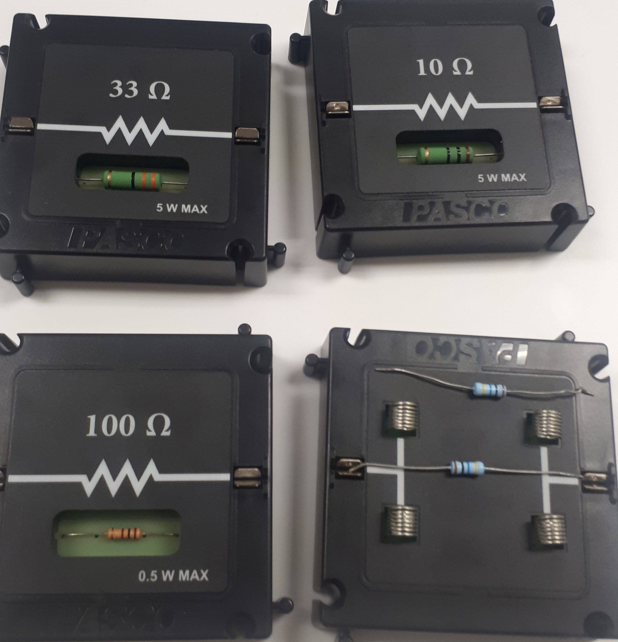
Figure 2: Some of the styles of resistor you will use in the lab.
2.3 Resistors in Series & Parallel
What if we had TWO resistors!?!? We could put them in the circuit in parallel, such as in Figure 3(a) or in series as in Figure 3(b). The total resistance would be different in each case, according to:
(1) 

Figure 3: Resistors in (a) parallel and (b) series.
A particularly useful application for resistors in series is to make a voltage divider. It’s just two resistors in series, then take the output voltage from across just the second one. The output voltage will be
(2) 
2.4 Capacitors
The hydraulic analogy of a capacitor is a flexible diaphragm in a pipe. Water can’t flow trough the diaphragm, but changes in water pressure can be transferred through. DC voltage charges up a capacitor (pushes the diaphragm) but current can’t flow through the capacitor. A capacitor is made of two electrical conductors separated by a dielectric material. The first time you learn about capacitors in lecture will likely be the classic parallel-plate capacitor, with two metal plates separated by vacuum/air.
A common circuit, and the one you will study today, is the ‘RC’ circuit made of a voltage supply, resistor, and capacitor (Figure 4). The capacitor is charged up by the DC supply, then a switch in the circuit is opened and the DC supply is no longer connected. The charge on the capacitor leaks out through the resistor. The time it takes for the voltage to reach  of its initial value is called the RC time constant
  , as shown in Figure 4. It’s called the RC time constant because
  . Pretty easy calculation there. Time constants like this come up a lot in exponential decay or growth, which are pretty general concepts in physics.
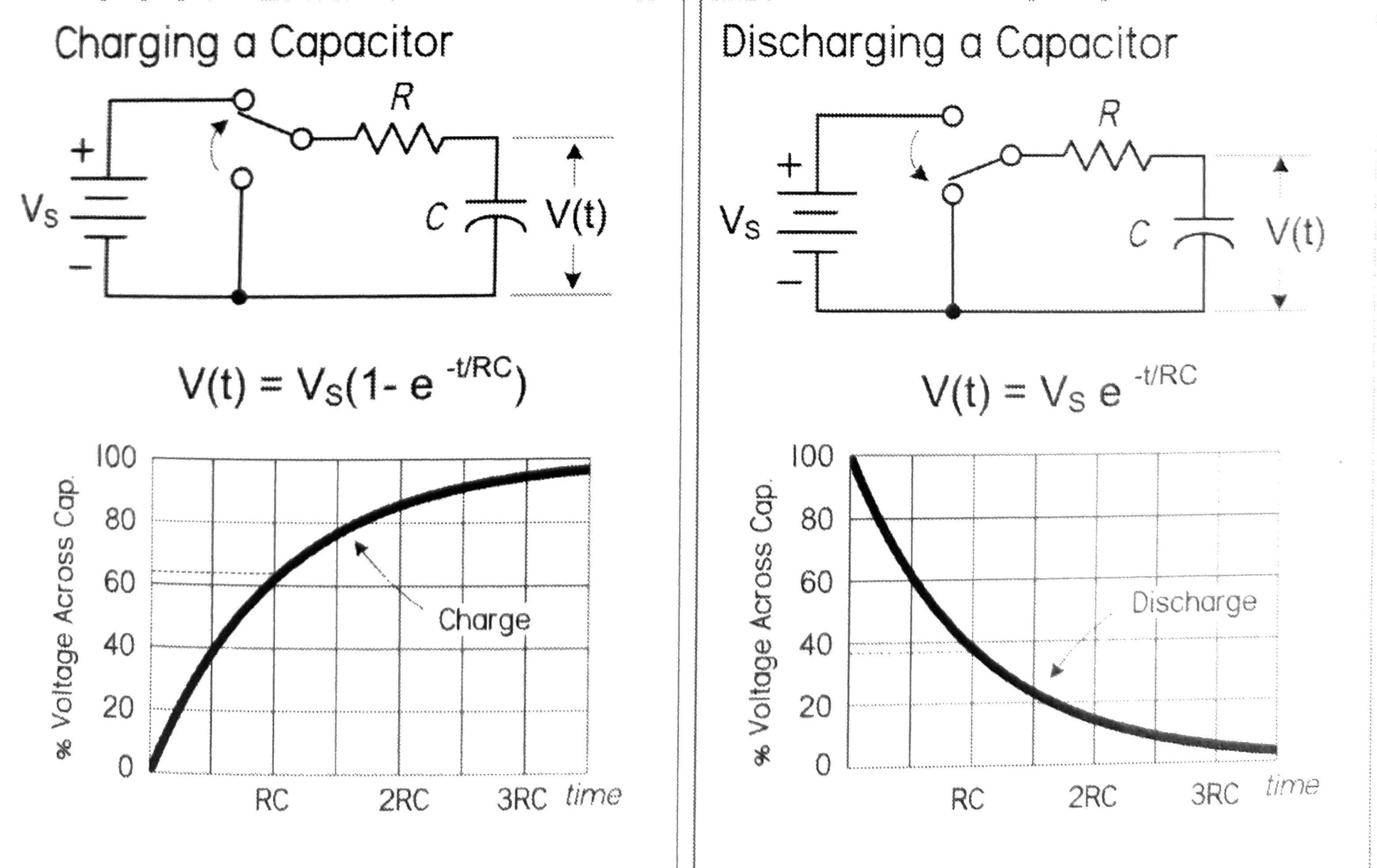
Figure 4: Voltage over time characteristics of a charging and discharging capacitor. Figure from Practical Electronics for Inventors.