Lab 4: RL Circuits and Filters
Introduction
2.1 Inductors
Inductors are very similar to capacitors in that they transform voltage into energy; a capacitor does this by generating an electric field, while an inductor does this with a magnetic field. An inductor is basically a solenoid (wire wrapped along a tube). The inductance of a solenoid is
(1) 
where  is the inductance,
  is the magnetic permeability of free space,
  is the number of turns in the solenoid,
  is the cross-sectional area of the solenoid, and
  is the length of the solenoid. You won’t have to use that equation in the lab, but it’s good to know that it exists.
While capacitors allow a quickly-changing voltage to pass through uninhibited, inductors allow slowlychanging or DC voltages through. When there is a change in the current going through the inductor, an electromotive force is induced that opposes the change in current that created it. Another way to say that is that an inductors impedance increases with frequency. Inductors are used to prevent sudden changes in circuits, like preventing radio frequency and electromagnetic interference from entering sensitive circuits.
2.2 RL Filters
We can make filters just like we did with capacitors and determine that the time constant is  . When you are building your circuits, pay attention to the order of the components and how that differs from your capacitive filters. Figure 1 shows a high and low pass filter using an inductor. Should look pretty familiar to the capacitor stuff you did in the last lab.
2.3 RLC Filters
When we combine all three of the components we’ve been studying so far, we get an RLC filter, as shown in Figure 2. The inductor will filter out high-frequency signals while the capacitor will filter low-frequency signals. If we choose our component values carefully, then we can create a filter that will only allow a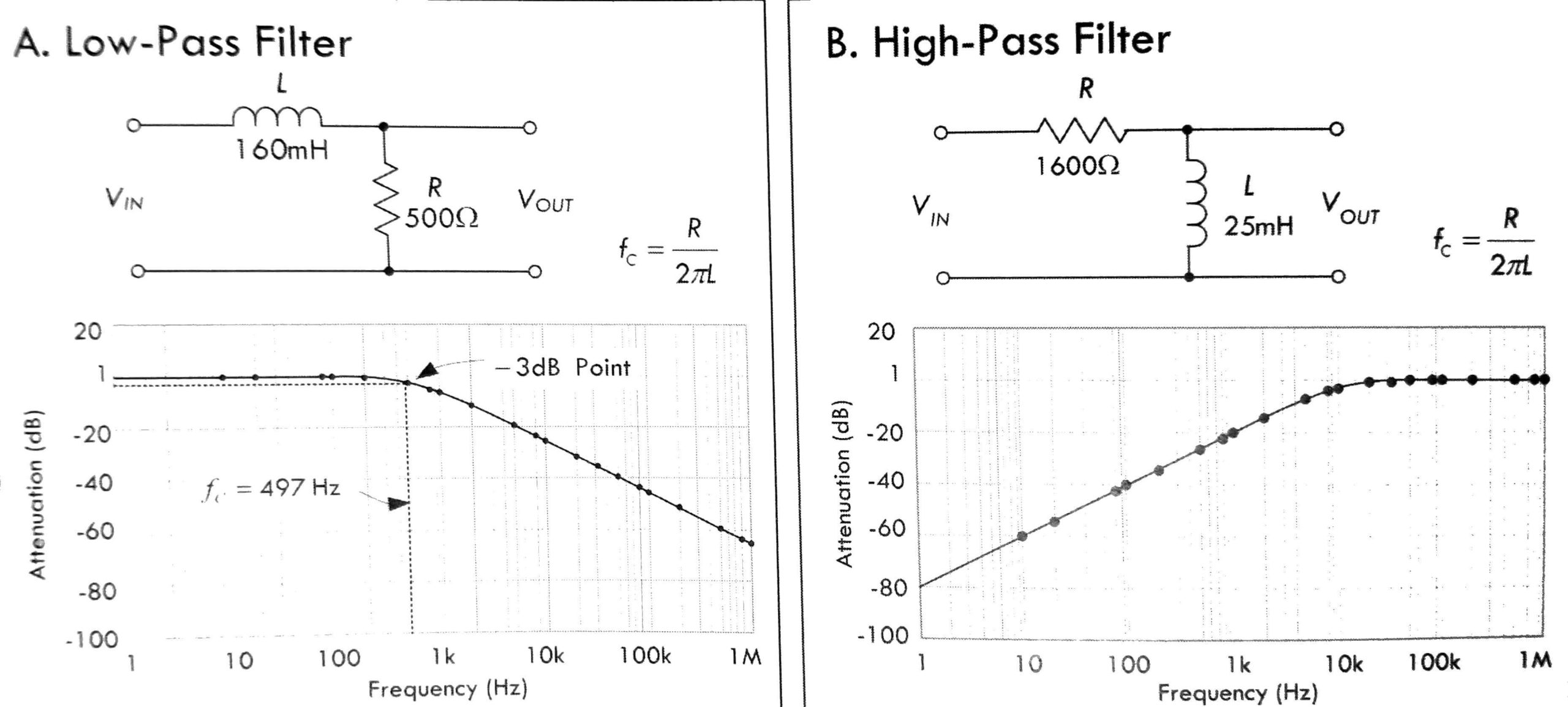
Figure 1: (A) Low and (B) high pass filters using an inductor. Figure from Practical Electronics for Inventors.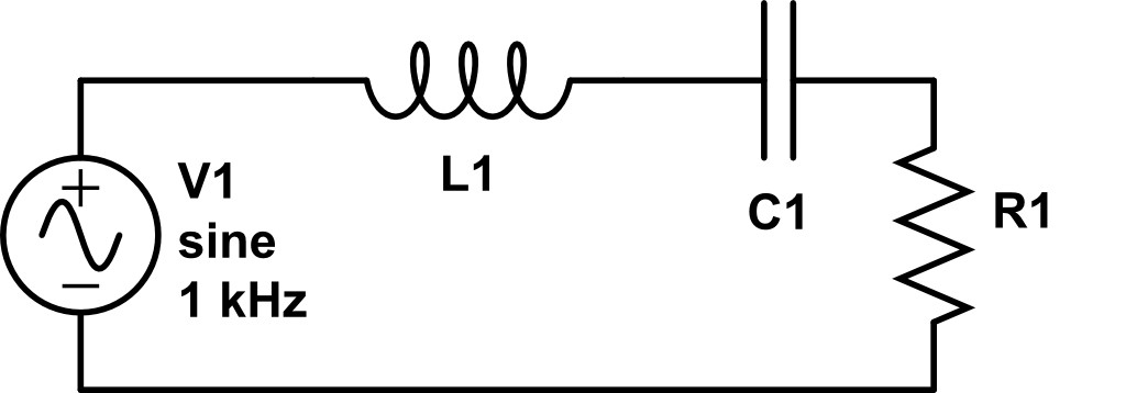
Figure 2: An RLC circuit that acts as a bandpass filter. The inductor and capacitor remove high and low frequencies, respectively.
narrow band of frequencies through the circuit. We say that the circuit has a resonant frequency, and other frequencies are attenuated. We call this a bandpass filter. The resonant frequency is
(2) 
When dealing with resonances, the width of the resonance (in frequency space) is just as important as the resonant frequency itself. We use the same definitions for cut-off frequency to define the band of allowed frequencies in the circuit. The ‘ ’ value of the circuit is used as a measure of the relative loss in the circuit:
(3) 
where  is the resonant frequency and
  is the difference between the high and low cut-off frequencies.
2.4 Damping
The resistor in the RLC circuit causes the amplitude of the oscillation to decrease over time – a phenomenon called damping. Damping typically falls into three categories: under-damped, over-damped, and critically damped. An example of these regimes is shown in Figure 3.

Figure 3: Examples of damped oscillations.  is underdamped,
  is critically damped, and
  is over-damped. Figure from Wikipedia