Lab 3: RC Circuits and Oscilloscopes
Introduction
2.1 Time-Averaging Signals
Your previous experiments were performed using DC voltage sources – the AA battery and the digital source. Now we start to consider AC (alternating current) signals, specifically periodic square, triangular, and sinusoidal waves. These waves are characterized by their frequency (or wavelength, if you want) and their amplitude. Frequency is pretty straightforward regardless of what shape the wave takes, but the definition of amplitude becomes important when comparing different waves. Here are a few common definitions:
(1) 
They are all equally valid as long as it is clearly stated which one is used, and your oscilloscope is able to directly measure these values.
2.2 Filters
In most DC applications, AC signals show up as noise i.e. a signal you don’t want (as shown in Figure 1). Sources of noise are varied: Most buildings have AC electricity at 60 Hz, so any measurements happening at that frequency may well be doomed from the start. Precise atomic measurements sometimes use microwaves that operate near the frequencies of some FM radio stations, and caution must be taken to avoid flooding your measurements with the local oldies station. Different experiments will have different needs; some need to avoid high-frequency noise, while high-frequency measurements may be trying to avoid low-frequency changes in the signal. Luckily, we have a circuit for that!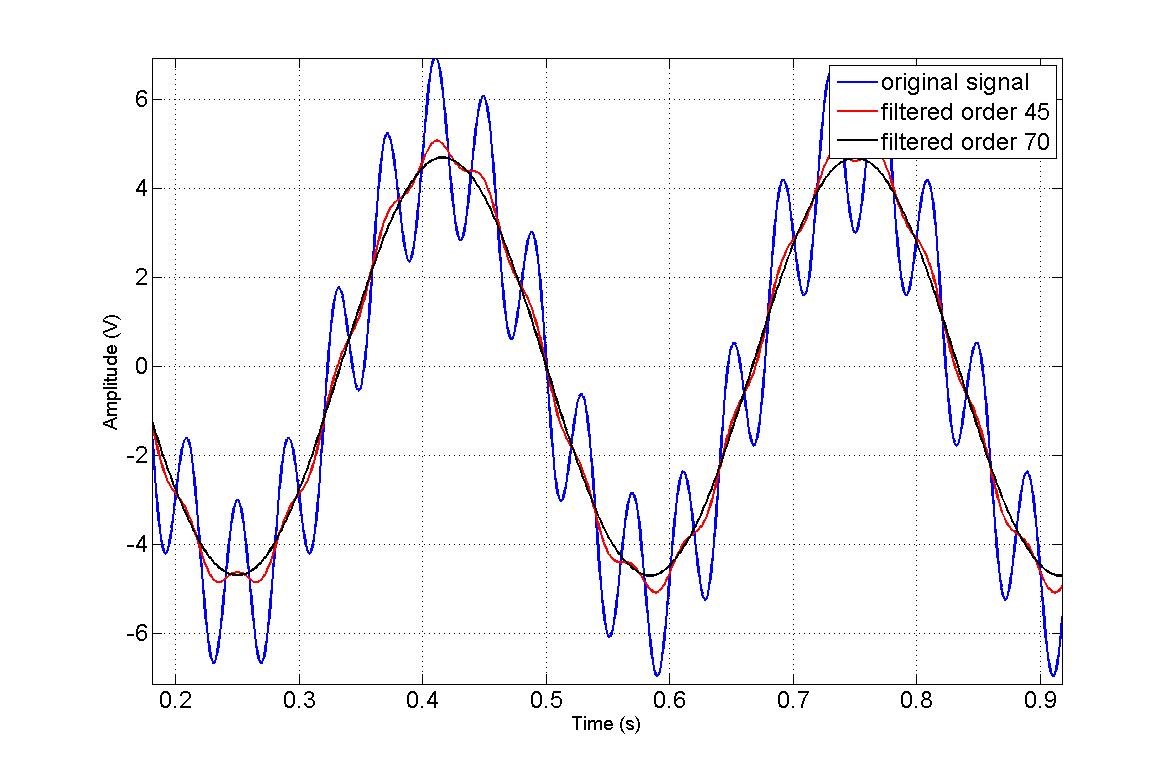
Figure 1: A signal with high-frequency noise filtered by a low-pass filter. The blue line is completely unfiltered (notice the high-frequency noise). The black line is completely filtered and only the low-frequency signal remains.
2.2.1 High-pass Filter
A simple high-pass filter is shown in Figure 2(a). The input voltage first passes through a capacitor, which acts like an open circuit to DC and low-frequency voltages; high-frequency voltages are not impeded by capacitors and pass through the filter unattenuated.
Comparison of frequency response is usually done using units of decibels (dB). Decibels are useful in making comparisons of the logarithm of some variable, typically power. When the amplitude of the wave drops to about 50%, then it’s at -3 dB, and we call that frequency the cut-off frequency.

Figure 2: (a) High and (b) low pass filters. Figure from Wikipedia.
2.2.2 Low-Pass Filter
A simple low-pass filter is shown in Figure 2(b). It’s the same as a high-pass filter, just with the R and C swapped. Now the high-frequency voltage will travel through the capacitor, directly to ground, and won’t make it to the output. Therefore, our output is just the DC and low-frequency aspects of the signal. Just like the high-pass filter, this frequency response is not instant. We use the same definition of cut-off frequency as with the high-pass filter.