THEORY
ELECTROLYTIC CAPACITOR
A capacitor is a device which stores charge. Its capacitance (C) is the charge it will hold per volt of applied potential, so that
(1) 
where Q is the charge, and V is the potential difference. Capacitance has SI units in the form of Farads (F) which are equivalent to Coulombs divided by Volts.
The simplest form of a capacitor is a pair of parallel conducting plates with surface area (A) separated by a distance (d). In this case, the capacitance is
(2) 
for plates in air or vacuum,  and it is called the permittivity of free space. It is a fundamental constant in electricity and magnetism as it describes the capability of an electric field to permeate a vacuum.
Large values of C are obtained by increasing A and minimizing the separation d. Rolling thin foil plates into a cylinder with a plastic layer in between gives a large area in a small package. But for capacitances much greater than 1 μF, a thinner insulator is needed. The electrolytic capacitor replaces one of the plates with a conducting solution of aluminum hydroxide. An extremely thin layer of oxide formed on the other (aluminum foil) plate insulates it from the electrolyte. By reducing the separation d in this manner, capacitances of thousands of μF are readily obtained.
However, some compromises are made. First, if the applied voltage makes the electrolyte positive with respect to the foil, the aluminum oxide will be broken down (chemically reduced), and the capacitor will short-circuit internally and possibly explode. All electrolytic capacitors have the polarity of the leads indicated on the package. Those used in this lab have a white band with minus signs indicating the negative side. Always connect the circuit so that the voltage across the capacitor is negative at this end, positive at the other. It is a good idea to check with a voltmeter before the second capacitor lead is connected.
Second, there is inevitably some internal leakage through the imperfect insulation layer. This effect is insignificant in this lab, as the capacitors will hold their charge for a few days.
There is a third effect which you may notice in your measurements. Because of chemical reactions between the electrolyte and the oxide layer, the capacitor does not strictly follow equation (1). In some ways it acts as a cross between a rechargeable battery and an ideal capacitor. This behavior is worse if the device has been charged up for several minutes. When no measurements are being taken, you should disconnect the capacitor from the circuit and short (i.e. connect together) the leads with a wire; this will help to give reproducible results.
THE RC CIRCUIT
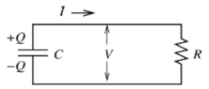
The circuit above is what we call an RC circuit (you might have guessed it, a Resistor and Capacitor circuit). If the capacitor has an initial charge (Q) and voltage (V) associated with it, then the charge will begin to decline once it is connected to the resistor (R). The rate of loss of Q through the resistor is the current I, which in turn depends on V through Ohm’s Law. This gives us a differential equation of
(3) 
where the – sign indicates that Q decreases. Substituting for V using (1)
(4) 
which has the solution (verify by substitution)
(5) 
The potential V therefore declines exponentially as well,
(6) 
or
(6a) 
The product, RC, has units of seconds (check this for yourself, with R is in  and C is in Farads) and is called the time constant of the circuit. It is the time at which the voltage or charge declines by a factor of
  .
.
For simplicity in the experiment, we are going to find a different time constant. Instead of the time at which V or C declines by a factor of  , our time constant will be when the voltage in the capacitor drops to half of its initial value. We will call this time constant
  (the Greek letter
  is pronounced “tau”). Analytically, we can find this value by:
![\[V(t) = V_0 e^{-\frac{t}{RC}},\]](https://ecampusontario.pressbooks.pub/app/uploads/quicklatex/quicklatex.com-7c5b7a66e74d9d076f0c38ba09d1dd6f_l3.png "Rendered by QuickLaTeX.com")
![\[t = \tau_{\frac{1}{2}} \Rightarrow V(t) = \frac{V_0}{2}\]](https://ecampusontario.pressbooks.pub/app/uploads/quicklatex/quicklatex.com-786ea46014a8f09b70137cc00b06b668_l3.png "Rendered by QuickLaTeX.com")
![\[\therefore \frac{V_0}{2} = V_0 e^{-\frac{\tau_{\frac{1}{2}}}{RC}}\]](https://ecampusontario.pressbooks.pub/app/uploads/quicklatex/quicklatex.com-a63a634a680731eb82cdaf6fe1f5e071_l3.png "Rendered by QuickLaTeX.com")
(7) 
(8) 