THEORY
DC CIRCUITS
An electric circuit is defined as a closed path containing circuit elements (generators, batteries, light bulbs, heaters, electric motors, etc.) joined by wires which facilitate the flow of electric charge. A circuit is said to have a Direct Current (DC) if the flow of charge within that circuit is uni-directional meaning the flow of charge is always in the same direction. This contrasts with Alternating Current (AC), where the flow of charge periodically reverses direction. We will not be examining AC current in this lab, but you may be familiar with it as the type of current that delivers power to your home.
Generators, batteries, or power supplies are sources of energy (mechanical, chemical and electrical respectively) that drive the flow of charge within a circuit. In order to understand this more intuitively, consider the flow of water within a system of pipes. The pumps that generate pressure and force the water to flow through the pipes play an analogous role to the sources of energy in an electric circuit. Light bulbs, heaters, and electric motors on the other hand, consume the energy to create light, heat, or mechanical energy. They are the equivalent to constricting the cross-sectional area of the pipe, or to the water wheels which convert the energy of the flowing water into heat or mechanical energy respectively.
Three main quantities, current, electric potential difference, and resistance, are used to describe an electrical circuit. The first two characterize the flow of charge, while resistance quantifies the opposition of current flow in a circuit element or circuit.
Basic Electric Quantities
The current (I) is the amount of electric charge per unit time flowing through a particular wire or component. Charge itself is measured in Coulombs and it comes in two types, positive and negative. Note that when it comes to defining current direction, positive charges flowing one way is equivalent to negative charges flowing the opposite way. In practise, conventional current is defined by the rate and direction of flow of positive charges. The SI unit for current is measured in Amperes (A) and is expressed as:
![\[1 A = 1 \frac{\text{Coulomb}}{\text{Second}}.\]](https://ecampusontario.pressbooks.pub/app/uploads/quicklatex/quicklatex.com-094e280b496e8156040ff2e9020aa487_l3.png "Rendered by QuickLaTeX.com")
The potential difference ( ) is defined as the difference in electric potential from point
  to point
  . The electric potential (
 ) at a point represents the potential energy per coulomb that a charge has at that point. The potential at a given point is the potential difference between that point and the ground (i.e. zero). Potential differences drive the current around the circuit. Potential is measured in SI units of volts (V):
![\[1 V = 1 \frac{\text{Joule}}{\text{Coulomb}}.\]](https://ecampusontario.pressbooks.pub/app/uploads/quicklatex/quicklatex.com-92bbe9b566bcde8578488f86c080b3e1_l3.png "Rendered by QuickLaTeX.com")
Note: the product of  times has the units of Joules/second or power (
 ) i.e.
  .
.
The resistance ( ) of the wire or circuit element represents how easily current can flow from points of higher electric potential to lower electric potential across the wire or circuit element. Going back to the analogy of flowing water, the resistance in an electric circuit is analogous to how much the flow of water is impeded. For example, reducing the diameter of the pipe which constricts the amount of water, or converting some of that flowing water’s energy into mechanical energy with a water wheel.
In electric resistors, energy is lost in the circuit via heat dissipated by the resistor, which we can quantify by investigating the power across the resistor. The SI unit for resistance is measured in ohms ( ) as
) as
![\[1 \Omega = 1 \frac{\text{Volt}}{\text{Ampere}}.\]](https://ecampusontario.pressbooks.pub/app/uploads/quicklatex/quicklatex.com-876a078de6ba630fe0ed5cb83f38e5c3_l3.png "Rendered by QuickLaTeX.com")
OHM’S LAW
The relation that relates all three of these electric quantities together is called Ohm’s Law. For many circuit elements, the resistance of that element can be described using Ohm’s law, which is explicitly written as:
![\[V = I R,\]](https://ecampusontario.pressbooks.pub/app/uploads/quicklatex/quicklatex.com-6aa2a4ffd7e928e65a2e5ace9e604e9c_l3.png "Rendered by QuickLaTeX.com")
where is the electric potential difference across the circuit element, is the current flowing through the circuit element, and is the resistance of that circuit element. Materials such as metals accurately obey Ohm’s Law, while other materials, such as air, do not.
We will be using Ohm’s Law throughout this entire lab to understand how electric quantities behave in different circuits with various resistors.
RESISTORS IN SERIES & PARALLEL
One of the easiest ways to find the current being drawn from a power supply is to find the equivalent resistance of that circuit. By definition, the equivalent resistance of a circuit is the value a single resistor would have which could replace an entire network of resistors within that circuit.
Resistors that are connected end-to-end are said to be connected in Series and are shown below.
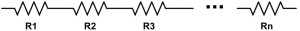
These resistors have the same current flowing through them and have various voltages depending on the amount of resistance each resistor has. If the current being drawn from the power supply is known, the voltage across each resistor can be determined using Ohm’s Law.
To determine the equivalent resistance of resistors connected in series, you simply add the resistances together, i.e.:
![\[\text{Series}: R_{eq} = \sum_{i=1}^n R_i = R_1 + R_2 + R_3 + \cdot \cdot \cdot + R_n .\]](https://ecampusontario.pressbooks.pub/app/uploads/quicklatex/quicklatex.com-e41e064ec20e7a2b1c865e1c58b1a2ec_l3.png "Rendered by QuickLaTeX.com")
This means that the more resistors you add in series, the higher the equivalent resistance of the circuit.
Alternatively, you can connect resistors in Parallel. Two resistors are said to be in Parallel with one another if their terminals are connected to the two same nodes. This is shown below for n resistors in parallel as
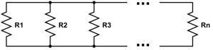
In this case, current goes through both resistors at the same time – not sequentially like it does for resistors in series. The voltage across multiple resistors in parallel is constant, while the current changes based on the various values of resistance.
The equivalent resistance for resistors in parallel is given as:
![\[\frac{1}{R_{eq}} = \sum_{i=1}^n \frac{1}{R_i} = \frac{1}{R_1} +\frac{1}{R_2} +\frac{1}{R_3} + \cdot \cdot \cdot + \frac{1}{R_n} .\]](https://ecampusontario.pressbooks.pub/app/uploads/quicklatex/quicklatex.com-8e46e34ea3c356d81b2fff76cc99d64b_l3.png "Rendered by QuickLaTeX.com")
KIRCHHOFF’S LAWS
Kirchhoff’s laws are simply convenient applications of the laws of conservation of charge and energy.
Kirchhoff’s first law (or junction rule, aka node rule) is based on the conservation of charge and states:
“At any junction point in a circuit, the sum of all currents entering the junction must equal the sum of all currents leaving the junction.”
Mathematically this is represented as:
![\[\sum_{k=1}^n I_k = 0,\]](https://ecampusontario.pressbooks.pub/app/uploads/quicklatex/quicklatex.com-b71e9d75781765ef6d9ff8d189a7e8de_l3.png "Rendered by QuickLaTeX.com")
where  is the total number of branches with currents
  ,
,  , …,
, …,  flowing towards or away from a junction (or node). A junction is any point in a circuit where current splits.
Kirchhoff’s second law (or loop rule) is based on the conservation of energy. It states that:
“The algebraic sum of the changes in electric potential around any closed path in the circuit must be zero.”
We represent this mathematically as
![\[\sum_{k=1}^n V_k = 0,\]](https://ecampusontario.pressbooks.pub/app/uploads/quicklatex/quicklatex.com-8c6652adc353b4426e0339a93d0d91f7_l3.png "Rendered by QuickLaTeX.com")
with voltages within the loop. A simple trick for utilizing the loop rule in practice is to add all the circuit elements which provide voltage to the loop (voltage sources, batteries with aligned polarity, etc…) and subtract the circuit elements that take voltage away from the loop (resistors aligned with the current flow, etc.…)
These laws provide a powerful yet simple framework in which you can analytically calculate the voltage and current for a wide variety of circuits. It will often involve solving systems of linear equations as they are usually applied to circuits which contain more than one loop. In fact, if you apply Kirchhoff’s loop law to a circuit which contains a single loop, you will find that it returns Ohm’s law for a set of resistors in series!