SETUP
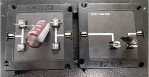
Figure 1: Image showing the capacitor and switch that its being used in this experiment. The capacitor is shown on the left, while the switch is shown on the right. Note: the white band on the capacitor indicates the negative terminal for the capacitor.
There are only two new circuit elements that we are going to introduce in this lab. One of them is the capacitor, while the other is the switch. Figure 1 shows an image with the capacitor and switch we are using in this lab. We will be using an external capacitor for our circuit.
The capacitor has a white band which indicates the negative sign. This switch does not have a polarity associated with it and can be oriented in either direction.