SETUP
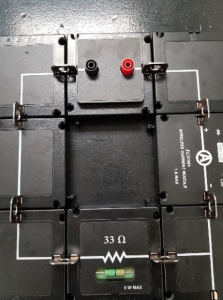
Our circuits in this lab are going to be built and designed with black building blocks which have a wire inside of them. The blocks are connected to each other with metal prongs which connect the wires within each block. Some of these blocks will contain various circuit elements (resistors, conductors, and inductors) which we will examine in the 1E03 labs. Figure 1 shows what the basic building block looks like.
 |
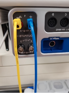 |
We have a power supply which is provided by PASCO’s 850 UNIVERSAL INTERFACE (the same device you were using for the 1D03 labs) which can create all sorts of various voltage sources. In these labs, we will only concern ourselves with DC voltage sources at very small amperages. The right-hand side of the universal interface has a red outlet for the source terminal and a black outlet for the ground terminal as shown in Figure 2.
With this interface, we can simultaneously provide a voltage source to our circuits, along with measure various electric quantities within our circuits. This is done through wireless voltmeters and ammeters which are connected via Bluetooth to the interface. You will need to set up the wireless voltmeter and ammeters before you can make any measurements through the Capstone software. The wireless voltmeter and ammeter are shown in Figure 3.
| Figure 3 – Wireless Voltage Sensor is the white box (also known as a voltmeter) and the Wireless Current Module is the black box (ammeter) which we will use in the lab. Notice how each box has a Bluetooth identifier on it and how the voltmeter can measure circuit elements in parallel, while the ammeter measures circuit elements in series. | 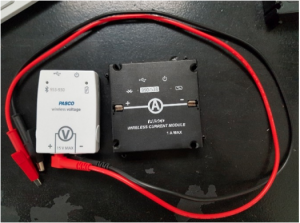 |
In Figure 4, we have two other electronic modules that we will be working with in this lab. One of them is a general extension which allows for outside circuit elements to connect to the PASCO circuits and the other is a module which connects AA batteries to the circuit.
| Figure 4 – Photo showing two of the electronic devices we will use in this lab. On the left is two sets of metal rings which allow for outside circuit elements to connect to the circuit which we call the coil module. On the right is a AA battery module which allows for a battery to be connected to the circuit. | 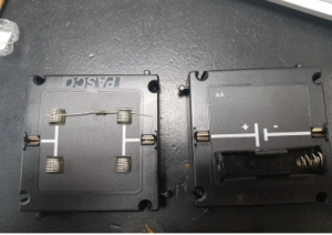 |
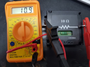
The final device we will be using is the digital multimeter. A multimeter is an ammeter, voltmeter, ohmmeter, and can have other functions as well. Digital multimeters are used in this lab primarily as ohmmeters (measuring resistance), while Capstone is primarily used to measure the current and voltage for us. Figure 5 is an image of the digital multimeter you will be working with in this lab. It is connected to a resistor indicating it is being used as an ohmmeter. An important thing to note is that the resistor must be completely detached from any circuit in order to get an accurate reading of the resistance. This is because an ohmmeter functions by supplying a small voltage source and creating a current which runs through the resistor and calculates the resistor’s value from a known current and voltage.
Figure 5 – A digital multimeter that is connected to PASCO’s resistor block. Notice how the dial on the multimeter is in the Ohm ( ) regime and the number is the order of magnitude for the measurement. This indicates that the multimeter is functioning as an ohmmeter. ) regime and the number is the order of magnitude for the measurement. This indicates that the multimeter is functioning as an ohmmeter. |
 |
The digital display can show 000 to 1999, with a decimal point at any position. As an example, in the “200 Ohm” range, the instrument can measure from 0.00 to 199.9 volts with a resolution of 0.1 Ohms. Although the readings may be repeatable to the least significant digit displayed, the manufacturer only claims the following calibration accuracies for the multimeter:
| Multimeter Functionality | Associated Error |
| DC Volts |  0.5% of reading 0.5% of reading |
| DC Amps | 1% of reading |
| Ohms | 0.75% of reading |
Setup for the voltmeter and ammeter:
1. Open the Capstone software on your computer.
2. Turn on the power for the Wireless Voltage Sensor and the Wireless Current Module. You only need to press the button once for these sensors to turn it on. To turn them off, press and hold their power buttons.
3. Select Hardware Setup and search for your voltage sensor and current module. Then choose those by double clicking on them in Capstone.
a. Within this lab, there are going to be 16 wireless voltage sensors and current modules running simultaneously. You can assign your wireless devices to your hardware setup by:
i. Searching for the 6-digit identifier on the sensor/module (it should be in the form of XXX-XXX).
ii. Selecting the 6-digit identifier that matches your devices from your Hardware Setup. If this is done correctly, you should have your voltmeter and ammeter properly assigned!
4. The Wireless Voltage Sensor and the Wireless Current module are sourced with a battery. So, make sure you turn them off at the end of the lab
***IMPORTANT*** This needs to be done before you can measure the current or voltage at any point in a circuit.