PART 3: Voltage Dividers
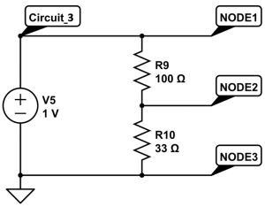
In this section, you will learn about voltage dividers. In the previous parts of the lab, you saw how resistors can be used to alter the current or voltage in your circuit. A voltage divider allows you to reduce the voltage that reaches certain parts of the circuit. Circuit_3, which is shown below, is an example of a voltage divider.
PROCEDURE
Derive a formula for the measured voltage at NODE2 (this should have been done in the prelab) and then build Circuit_3 using these resistor values. You will need to set up the power supply in the same way you did for Circuit_1 in PART 1. Here is a reminder of that procedure.
Setup for the power supply:
- Select signal generator under tools on the left-hand side.
- Under 850 Output 1, select the waveform of DC.
- Set the voltage to 1 Volt and turn it on.
a. Make sure you only turn on the power supply when you are about to make a measurement. DO NOT keep the power supply on at all times.
In Pasco Capstone, create a graph of Voltage vs. Time. Using Circuit_3, measure the voltage between NODE1 and NODE2, the voltage between NODE2 and NODE3, and then record these values in Table 1 of the Results section for PART 2.
Question 6
Question 7