PART 1: Measuring Electric Quantities with Ammeters & Voltmeters
Electric circuit elements can be measured directly using ammeters to measure current in Amps (amperage) and voltmeters to measure the voltage in Volts. The way in which we measure amperage or voltage is different between the two. To see how voltmeters and ammeters are used to measure voltage and amperage respectively, we are going to examine the simplest circuit we can, which is shown in Figure 6.
The circuit shown in Figure 6 demonstrates how we measure the amperage of a resistor through an ammeter and how a voltmeter measures the voltage of a resistor. The voltmeter needs to be placed in parallel to the resistor R and the ammeter needs to be placed in series to the resistor R. This is true for any type of circuit element (conductors, inductors, transformers, etc.…). Voltmeters can be thought of as resistors with an ideally infinite resistance meaning they draw no current from the voltage source. Ammeters on the other hand, are ideally resistors of zero resistance meaning they do not draw any power from the voltage source. In practice however, nothing is truly infinite or zero, meaning they will have some internal resistance associated with them which can slightly offput the measured values.
| Figure 6 – Simple circuit containing a voltage source, resistor, ammeter, and voltmeter. Notice how the voltmeter is introduced in parallel to the resistor and how the ammeter is introduced in series to the resistor. | 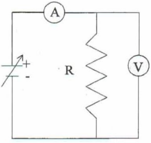 |
PROCEDURE
Before starting this procedure, make sure you have properly setup your wireless voltmeter and your wireless ammeter. Instructions for this can be found in the “SETUP” section of the lab manual.
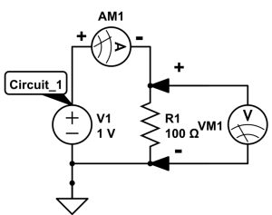
- Create Circuit_1 using the building blocks and the appropriate placement for the voltmeter (VM1) and the ammeter (AM1). Make sure the resistor R1 is at 100 Ohm’s.
- Setup the power supply with the following instructions:
- Select signal generator under tools on the left-hand side.
- Under 850 Output 1, select the waveform of DC.
- Set the voltage to 5 Volts and turn it on.
**IMPORTANT** Make sure you only turn on the power supply when you are about to make a measurement. DO NOT keep the power supply on at all times.
- Measure the voltage and amperage across the resistor R1 and record your answer in the MS Word report under the Results section for PART 1. To measure the voltage of a circuit element with the wireless voltage sensor:
a. Take the Wireless Voltage Sensor and insert a red clamped wire into the red outlet and a black clamped wire into the black outlet. The red outlet represents the positive terminal for the voltmeter, and the black outlet represent the negative terminal for the voltmeter.
b. Connect the red clamp to the metal prong on one side of the circuit element, and the black clamp to the other side of the circuit element.
c. With the power supply setup properly, select the voltage as the y-axis for the graph generated. This will measure the voltage over time over the desired circuit element.
To measure the amperage of a circuit element:
a. Take the Wireless Current Module and connect it to the other modules (building blocks) at the desired location.
b. With the power supply setup properly, select the current as the y-axis for the graph generated. You can simultaneously measure the current and voltage by creating a new graph in Capstone and setting that y-axis to current. This will measure the current over time over the desired circuit element.

CHECKPOINT
(Ask the TA to check your circuit and if you have setup the voltmeter/ammeter correctly)
- Using Ohm’s law, calculate the current you would expect the resistor R1 to draw given the voltage of the power supply.
Question 1
Does the measured value for current match the calculated value for current from Ohm’s law for Circuit_1? Explain why or why not. Hint: How close is your measured voltage value to the set voltage of the power supply? To answer this question quantitatively, calculate the percentage difference between the expected and experimental values using the following formula for the percent difference test:
If  , then
  within 10% uncertainty, where A and B are theoretical and experimental values, respectively.
Question 2
 do you think you would obtain an accurate measurement of voltage from the voltmeter? Explain why or why not. (Hint: Think about the internal resistance of a voltmeter)
Question 3