SETUP
In this lab, you will measure the electric potential and electric field for a two-dimensional system consisting of conducting lines rather than plates. However, you can imagine the planar system as a slice through a three-dimensional capacitor consisting of a pair of long flat plates. As long as the system is uniform as you move along the long axis, so that every slice perpendicular to the axis is identical, studying the field in one slice will tell us everything about the corresponding 3 dimensional object.
It is important to make this reduction to a planar object, as we can then substitute a piece of weakly, but evenly conducting paper for the insulator between the plates. If the resistance of the paper measures in the tens of kilohms from plate to plate, then placing the probe of a voltmeter (resistance of 1 Mega Ohm) on the paper will not perceptibly alter the potential at that point. However, if we were to try this with air as the insulator (resistance  ohms or greater), the probe would essentially be short-circuited through the meter. The very small current flowing through the air to maintain the potential difference would instead flow through the meter, and the meter’s much lower resistance would cause the potential difference we were trying to measure to drop almost to zero.
In this lab, you will be introduced to the digital multimeter. A multimeter is an ammeter, voltmeter, ohmmeter, and can have other functions as well. A digital multimeter is used in this lab as voltmeter (measuring Direct Current or “DC” voltage), while PASCO Capstone software is primarily used to supply the power for us.
Figure 1 is an image of the digital multimeter (left) and the voltage output and ground for the power supply from the PASCO software (right) that you will be working with in this lab. The digital display on the multimeter can show 000 to 1999, with a decimal point at any position. Although the readings may be repeatable to the least significant digit displayed, the manufacturer only claims the following calibration accuracies for the multimeter:
| Multimeter Functionality | Associated Error |
| DC Volts |  0.5% of reading 0.5% of reading |
| DC Amps | 1% of reading |
| Ohms | 0.75% of reading |
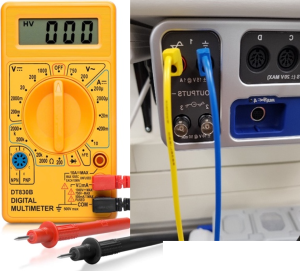
Figure 1 – Left: A digital multimeter. To use the multimeter to measure Direct Current or “DC” voltage, the dial on the multimeter must be in the DC regime indicated by a V with a straight line (top left). Right: Voltage output and ground for the power supply from the PASCO 860 UNIVERSAL INTERFACE. The yellow wire is in the positive outlet and the blue wire is the ground outlet.
APPARATUS
Potential measurements are made at the probe connected to the positive end of the voltmeter which can be moved around the conducting paper. Note the x and y labels that denote horizontal and vertical axes on the conductive sheet.
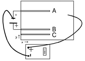
Figure 2 – Experimental Apparatus
Caution: The conductive sheets used in this experiment are very fragile and mounted on a soft foam backing. The following practice is necessary to prevent damage to the sheets.
- Contact should be made only through the leads of the digital multimeter.
- Never apply force to the contact – use the weight of the contact lead only.
- Never attempt to write on the conductive sheet.
- Avoid touching the conductive sheet, or resting your hand on it. Conductive salts on your skin can spoil the uniform resistance of the sheet.
- Never apply masking tape to the conductive sheet since removing the tape can destroy the board.
- Do not use rulers or other sharp objects on the conductive sheet to avoid scratching it.