PART 4: kIRCHOFF’S RULES – CIRCUIT WITH TWO LOOPS
This part of the lab will focus on verifying Kirchhoff’s Laws for a circuit with two loops (Circuit_4).
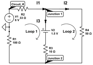
Figure 7 – Consider Circuit_4 shown above. In the pre-lab, use Kirchhoff’s loop and junction laws to provide three equations for the currents I1, I2, and I3 in terms of the resistors R1, R2, R3, and R4 and the two voltage sources V1 and V2. Then use these equations to calculate I1, I2, and I3. You will show your calculations in Question 9.
PROCEDURE
Before starting this procedure, make sure you have written down the equations for Kirchhoff’s loop/junction laws, properly set up your wireless voltmeter, and properly set up your wireless ammeter.
- BEFORE YOU SET UP THE CIRCUIT, measure the resistance for each resistor in Circuit_4, and record their values in the report under Table 2. To measure the resistance, you are going to use the Ohmmeter functionality of your multimeter. To do this:
a. Set your multimeter to measure resistance. This is indicated by the capital omega ( ) section of the multimeter.
i. Note: with the resistors we are working with in this section, you will only need to use the “2000” and “200” scale setting.
b. Note: you will need to use the double-ended banana cords (the same ones connected to the Pasco interface could be temporarily disconnected) to take measurements with the multimeter. The alligator clip cords do not connect into the multimeter terminals fully. Once the cables are connected to the multimeter, simply touch the other ends of the cables to the metal prongs on either end of the resistor block.
i. Note: it does not matter which orientation the positive and negative terminals are, since resistance is non directional.
c. After a few seconds, record the value shown on the ohmmeter into Table 2 of your report for each resistor.
d. The ohmmeter functionality of the digital multimeter has an associated uncertainty of  0.75% of the value read.
Note: The 50 resistor is not ingrained in the building block (inside the block with its value printed on the block) and will instead be connected via outside terminals that look like metal rings.
- Setup Circuit_4 as shown above with the power supply set to 6V as a DC waveform with the battery connected. Make sure you have correctly aligned the polarity of your battery and power supply. To setup the power supply:
a. Select signal generator under tools on the left-hand side.
b. Under 850 Output 1, select the waveform of DC.
c. Set the voltage to 6 Volts and turn it on.
d. Make sure you only turn on the power supply when you are about to make a measurement. DO NOT keep the power supply on at all times.

CHECKPOINT
(Ask the TA to look at your Circuit_4, your measured values for resistance, and the equations you wrote for Kirchhoff’s Laws)
- With the circuit assembled and powered up (set V1 to 6V), measure the voltage across each resistor, and each voltage source (V1 and V2). Record your values for the various voltages in Table 3. To measure the voltage of a circuit element:
a. Take the Wireless Voltage Sensor and insert a red clamped wire into the red outlet and a black clamped wire into the black outlet. The red outlet represents the positive terminal for the voltmeter, and the black outlet represent the negative terminal for the voltmeter.
b. Connect the red clamp to the metal prong on one side of the circuit element, and the black clamp to the other side of the circuit element.
c. With the power supply setup, select the voltage as the y-axis for the graph generated. This will measure the voltage over time over the desired circuit element.
- Measure the currents in each branch at Junction 1 and Junction 2. Remember, the ammeter must be in series, that is, the ammeter must be inserted as part of the circuit. Record your values in Table 4. Use the direction of the current shown in Circuit_4 when deciding whether a current should be recorded as positive or negative.
a. Note: If you use the conventional direction of current flow as that of positive charges, then the current flow out of the most positive voltage source must register as positive on your meter. If the contrary is true, reverse the meter connections and note the direction of current flow for future reference.
To measure the amperage of a circuit element:
b. Take the Wireless Current Module and connect it to the other wires at the desired location.
c. Select the current as the y-axis for the graph generated. This will measure the current over time over the desired circuit element.
- Add the measured currents at each junction and compare the results with Kirchhoff’s Junction law. Sum the measured voltages around each of the closed paths in the circuit and compare your results to Kirchhoff’s loop laws that you derived.
- Add the theoretical values you obtained for the currents in the pre-lab section to Table 4 and compare them to the measured values.
Question 8
Question 9
Do your experimental values for the currents I1, I2, and I3 match the theoretical values you obtained in the pre-lab section? Show your calculations for currents here and compare to experimental values using the percent difference test.
If you did not complete the Pre-lab and are short on time, use the provided values for I1, I2, and I3. However, note that there are some marks associated with showing these calculations.
Question 10