Introduction
PURPOSE
The purpose of this experiment is to examine how the distribution of mass in a body affects its moment of inertia and to observe how changing the moment of inertia affects its rotational dynamics. There are some systematic uncertainties present in this experiment and you have an opportunity to try to determine what they are.
INTRODUCTION
In a translational system, “mass” is that characteristic of a body which determines how effective a given force will be in producing a translational motion. Mass might be considered a measure of the quantity of matter in a body. In a rotational system, “moment of inertia” is the rotational analogue of mass. That is, the moment of inertia is that characteristic of a body that determines how effective a given torque will be in producing a rotational motion. The moment of inertia of an object depends not only on the mass of the object, but also on how the mass is distributed with respect to the axis of rotation.
The kinetic energy of a rotating body likewise depends on its mass distribution. Those parts of the body farthest from the axis of rotation have the largest speed and hence the largest kinetic energy. In fact, it is the moment of inertia introduced above that, along with the angular speed, determines the kinetic energy of a rotating body.
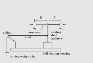
A simple system, whose moment of inertia can be easily calculated, is one with two equal point masses equidistant from the axis of rotation. The system you will investigate is slightly more complicated. It consists of a rotating shaft and cross bar on which two disks of total mass ![]() are located at a distance
are located at a distance ![]() from the axis of rotation (see Figure 1 in the experimental setup section). It is designed so that the distance
from the axis of rotation (see Figure 1 in the experimental setup section). It is designed so that the distance ![]() can be easily changed and, hence, the moment of inertia,
can be easily changed and, hence, the moment of inertia, ![]() , varied. By measuring both the rotational kinetic energy and the angular speed of this system,
, varied. By measuring both the rotational kinetic energy and the angular speed of this system, ![]() can be determined in a dynamical manner.
can be determined in a dynamical manner.
The moment of inertia, ![]() , consists of two parts: there is the moment of inertia of the shaft and crossbar, called
, consists of two parts: there is the moment of inertia of the shaft and crossbar, called ![]() , and the moment of inertia of mass
, and the moment of inertia of mass ![]() at distance
at distance ![]() , called
, called ![]() . Thus
. Thus
(1) ![]()
In this lab, we want to find ![]() , by itself, for comparison with its theoretical value. So, we use
, by itself, for comparison with its theoretical value. So, we use
(2) ![]()
where both quantities on the right side of this equation will be obtained from measurements of the motion of the system. The theoretical value for the moment of inertia of a point mass ![]() situated at a distance
situated at a distance ![]() from the axis of rotation is
from the axis of rotation is
(3) ![]()
We will test this equation in two ways using the experimentally determined values of ![]() and the measured values of
and the measured values of ![]() .
.
We will now determine the theoretical expression for moment of inertia of our system, illustrated in Figure 1. The hanging mass ![]() is dropped from a height, causing a rotation in the crossbar system. The gravitational potential energy of the falling mass is converted into the translational kinetic energy of this mass and the rotational kinetic energy of the crossbar system. Conservation of energy requires that the initial total energy (potential energy (PE) plus kinetic energy (KE)) of the system is equal to the total final energy (PE plus KE) of the system.
is dropped from a height, causing a rotation in the crossbar system. The gravitational potential energy of the falling mass is converted into the translational kinetic energy of this mass and the rotational kinetic energy of the crossbar system. Conservation of energy requires that the initial total energy (potential energy (PE) plus kinetic energy (KE)) of the system is equal to the total final energy (PE plus KE) of the system.
Initial conditions (just before the system is released):
- The system is at rest, so the initial KE is 0
- If the final (lowest) position of the driving mass
 is taken to be the zero point for the potential energy, then the initial PE is
  , where
  is the initial height of
  above the final lowest position (i.e.,
  ).
). - Hence, the initial total energy of the system is

Final conditions:
- The driving mass has a translational KE,
 where
where  is its final speed.
 - The rotating assembly (crossbar, or crossbar + masses) has a rotational KE,
 where
where  is the final angular speed.
 - The driving mass has a final PE of 0 .
- Hence, the final total energy of the system is

From conservation of energy:
(4) ![]()
or
(5) ![]()
If ![]() and
and ![]() are known, then
are known, then ![]() can be determined from this expression. In order to calculate
can be determined from this expression. In order to calculate ![]() from
from ![]() , the time it takes for
, the time it takes for ![]() to fall a height
to fall a height ![]() , we use the constant acceleration formulas from kinematics,
, we use the constant acceleration formulas from kinematics,
(6) ![]()
to obtain
(7) ![]()
Finally, as the string which is wound around the shaft has the same speed as the driving mass ![]() ,
,
(8) ![]()
where r is the radius of the shaft. Substitute Eqs. (7) and (8) into (5) and simplify to get
(9) ![]()
EXPERIMENT: MOMENT OF INERTIA
SETUP

Figure 1: Schematic diagram of the crossbar moment of inertia system.

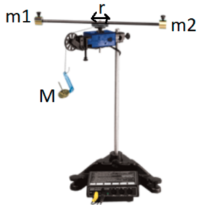
Figure 2: Image showing relevant quantities for the crossbar moment of inertia system.
