Lab 5: The Bridge
Lab 5: The Bridge
Remember how to properly turn on your power supply (if you forget, go back to last week’s lab). As a reminder: EVERY CIRCUIT SHOULD BE CHECKED BY A TA BEFORE IT IS FULLY CONNECTED TO THE POWER SUPPLY.
Exercise 1: What do you remember from last week …
a) Consider the circuit shown below.
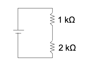
b) Set up the circuit and check your predictions with the multimeters.
Exercise 2:
a) Now imagine adding a second branch which is identical to the first…
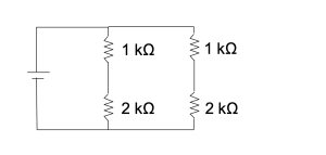
… and then inserting a voltmeter like this…
What would you expect the reading on the voltmeter to be? (Remember that a voltmeter measures the difference in potential between the two points.)
b)With the power supply set to about 2 V, build the circuit and test your prediction.
Exercise 3
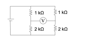
a) Now suppose you switched out the resistors in the second branch, like this:
b) In summary, if I were to give you the circuit below, tell you the magnitudes of RA, RB, and R, and also tell you that the voltmeter reads zero, how would you calculate X?
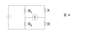
A circuit like this one is called a bridge (as in, the voltmeter forms a bridge between the two branches). Bridge circuits are used to make accurate comparisons of resistances or potentials by a null method (i.e. having the voltmeter reading go to zero). In such a measurement, it is convenient to replace the two fixed resistors, RA and RB with a potentiometer…
Exercise 4: The Potentiometer
A potentiometer (or pot for short) is a variable resistor. It has electrical contacts at each end and a third contact which can be moved along the resistor from one end to “divide” the resistor into two pieces. The moving contact is called the wiper.
Your circuit board platform has a potentiometer built into it. (It’s the round thing with the dial.) If you flip the platform over, you’ll see the three connections from the pot to the connectors labeled CW, CCW, and Wp on top of the platform.
a) Using one of your multimeters as an ohmeter, measure the resistance between the CW and CCW connectors.
R =
Rotate the black knob on the pot while monitoring this resistance. (Nothing should change, since in this configuration you are measuring the entire resistance of the pot.)
b) Now measure the resistance between the CW and Wp connectors and then between the CCW and Wp connectors. How are the resistances related?
If you rotate the knob now, what happens to these resistances?
c) Dial the scale on the pot down to zero. (Be careful. Some of the pots won’t dial all the way down. Don’t force them or they’ll break.) Which resistance is closer to zero? CW to wiper, or CCW to wiper?
d) Connect an ohmeter to whichever set has a resistance closest to zero. Now dial the pot up slowly and read the pot scale while measuring the resistance with the meter. Does the scale on the potentiometer provide a reasonably good measure of the resistance?
Exercise 5: Putting it All Together…
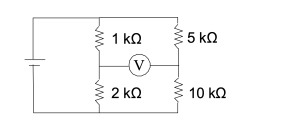
In this section, you are going to use a bridge and a potentiometer to find the value of an unknown resistance. BUT FIRST, it might be a good idea to practice with a known “unknown” to make sure your circuit (and arguments) are working correctly. Build this circuit:
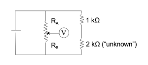
RA and RB are the divided resistances of the potentiometer, and the voltmeter is connected to the wiper Wp. Adjust the potentiometer until you get a null reading on the voltmeter (i.e the voltmeter reads zero) and then calculate the “unknown” resistance using RA, RB, and the known 1 kΩ resistor, as you described in the last part of the bridge exercise. Make the measurements and see if you correctly predict the magnitude of the “unknown” resistor.
MAKE SURE A TA CHECKS THIS CIRCUIT BEFORE MOVING ONTO YOUR UNKNOWN RESISTOR.
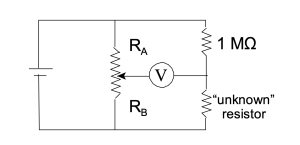
Once you’ve perfected your argument, ask your TA for the (REALLY unknown) unknown resistor. Replace the 1 kΩ resistor with a 1 MΩ resistor for this measurement.
Exercise 6: The Problem with Meters…
a) Consider the simple circuit shown here.
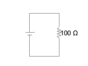
b) Use a voltmeter to set the power supply output to about 0.1 V. (Yes, that’s very small.)
c) Modify the diagram by adding an ammeter in an appropriate way to measure the current through the 100 Ω resistor, and then build the circuit using the blue meter as the ammeter.
d) Measure the current with the ammeter set on different scales.
On the 200 mA scale I =
On the 20 mA scale I =
On the 2 mA scale I =
e) How do these compare to what you expect to measure? Do you see the problem?
Exercise 7
a) An ammeter is also a resistor. When you add it to the circuit, it changes the circuit. The battery puts out less current, because the circuit now looks like two resistors is series.
Consider, for example, the measurement on the 2 mA scale. How large would the resistance of the ammeter have to be to produce the measured current?
b) You can measure the ammeter resistance directly like this: disconnect your meters from the circuit. Use the orange meter as an ohmmeter to measure the resistance across the ammeter inputs of the blue meter:
resistance of the blue meter on the 200 mA scale =
resistance on the blue meter on the 20 mA scale =
resistance on the blue meter on the 2 mA scale =
Are these resistances consistent with your current measurements on each scale?
c) The resistance of the ammeter must affect every measurement you take with it and yet when you compared prediction and measurement in Exercise (1), using ΔV = IR , it seemed to work. Why didn’t you notice this problem?
d)
e) With these results in mind, explain why you should never put an ammeter directly across a power supply.
Exercise 8
If an ammeter alters a circuit, then you might expect a voltmeter to do the same…
a) Use the orange multimeter as an ohmeter to measure the resistance of the blue meter when it is operating as a voltmeter. What do you observe?
b) Reconnect the circuit from Exercise (6a) with the blue meter as the ammeter. With the ammeter set on the 200 mA scale (which we know will cause the least interference with the circuit) measure the current.
Now, attach the orange voltmeter. How does it affect the circuit? Why?
c) Under what circumstances might a voltmeter adversely affect the measurements in a circuit?
d)