Lab 4: DC Circuits II
DC Circuits II
Placement of Ammeters and Voltmeters in a circuit.
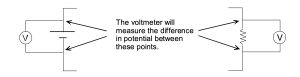
Power supplies and resistors cause changes in the potential. These changes can be measured with a voltmeter. You would describe a voltmeter as measuring the potential (difference) across a resistor or a power supply. In a simple measurement, the voltmeter goes into a circuit in parallel to the circuit element so that it samples both sides of the element.
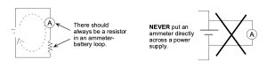
An ammeter measures current (NOT differences in current). Since the current can vary from place to place in a circuit, you should imagine building your circuit, and then breaking it open to sample the current flow at a particular place with your ammeter. An ammeter must always appear in series with a resistor in a circuit.
Exercise 1
REMINDER: GET ALL CIRCUITS CHECKED BY TAS BEFORE FULLY CONNECTING THEM TO THE POWER SUPPLY.
a) Start by checking that your power supply is working. Power up the supply following the instructions at the table.
Connect a (blue) voltmeter across the power supply, like this…
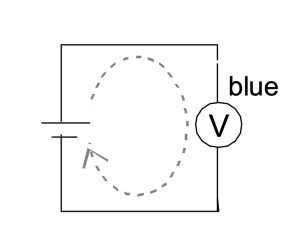
… and measure the potential difference across the power supply as you turn the voltage control knobs. If all is well, you should be able to see the changing potential difference on your voltmeter. Set the power supply to 6 V (for the next exercise).
What happens if you reverse connections at the power supply?
b) Build this circuit:
Connect the (blue) voltmeter directly across the “legs” of the resistor. What value would you expect it to measure? Why? Are there any assumptions in your argument?
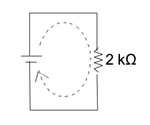
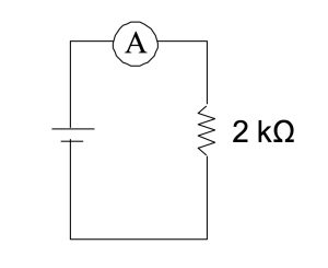
c) Build this circuit:
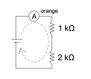
With the power supply set to 6 volts, what is the current measured by the ammeter?
Redraw the circuit with the ammeter positioned to measure the current between the two resistors. Would you expect to measure more, less, or the same current? Why? Do the measurement and check.
Exercise 2
Using the two multimeters, you’ll now be able to measure both the current (I) through the resistor, and the voltage (V) across the resistor, as you change the voltage on the power supply. Set up this circuit:
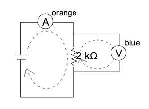
Measure the current at 4 different voltages and calculate the ratio ΔV/I :
ΔV = 2.0 V: I = ΔV/I =
ΔV = 4.0 V: I = ΔV/I =
ΔV = 6.0 V: I = ΔV/I =
ΔV = 8.0 V: I = ΔV/I =
Exercise 3
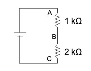
a) Consider this circuit:

If the difference in potential between A and C is 6 V, what would you expect the difference in potential to be between A and B? Between B and C? Why?
b) How would you add a voltmeter to the circuit to measure the voltage between A and B? (Draw it on the diagram.)
Build the circuit and measure ΔVAB and ΔVBC to test your prediction. (The TA will want to see the actual measurements.)
c) Suppose that you were to replace the second 1 kΩ resistor with a 2 kΩ resistor, like this:
For the same 6V battery potential, predict the voltage drop across each resistor.
d) Build the circuit and test your predictions.
e) Now consider a general circuit…
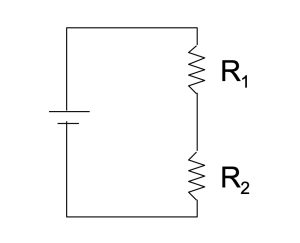
Write an expression for the voltage drop across each of the resistors in terms of ε, R1 and R2 .
ΔV1 =
ΔV2 =
Exercise 4
a) Consider this circuit:
With the power supply voltage set to 6V, what would you expect the current measured by the ammeter to be?
b) Now, you were to add a second resistor to the circuit, as shown in this diagram…
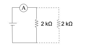
Compared to the one resistor loop in part (a), do you expect the current to increase, decrease or stay the same?
c) Set up the circuit in a) and then in b) to measure the current and test your prediction. Use the blue meter as the ammeter. (The TA will want to see your measurements.)
d) Here is an interesting thing to try. Leave the 2 kΩ resistors in parallel on the board but completely disconnect them from the power supply. Now use one of the multimeters as an ohmmeter to measure their resistance.
Is this result consistent with what happened to the current when you went from a single resistor to the parallel combination?
e) Consider this variation of the circuit:
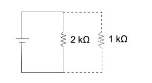
For the same 6V from the power supply, what would you expect the current in each resistor to be?
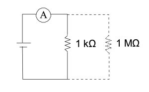
f) How would you add an ammeter and voltmeter to the circuit if you wanted to measure the current through, and the voltage across, the 1 kΩ resistor? Add them to the diagram.
g) Build the circuit and test your predictions. (Use the blue meter as the voltmeter.)
h) Consider the general case:

What is the current in each resistor? What is the current measured by the ammeter?
I1 =
I2 =
IA =
i) One more variation
What would you expect the ammeter to measure in this case?
I =