Lab 3: DC circuits I
For this lab, take turns building the circuits so that every member of your group has a chance. The TAs will want to make sure everybody is able to build circuits so have each group member build a different circuit.
While building a circuit, always leave one side of the power supply disconnected. You will only connect it once the TA has checked your work.
Part A: Simple Circuits
A1. Have a group member connect the following circuit using wires

Find the resistors that you need by reading the bar codes.
Build the circuit by starting at the red connector on the power supply (the long bar on the battery diagram) and working your way around the loop.
Take the circuit completely apart.
A2. Have a different group member connect the following circuit using wires

Build the battery loop first.
Add the second loop.
Take the circuit completely apart.
A3. Have a different group member connect the following circuit using wires

Part B: Using the Circuit Board
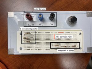
Build these circuits using the circuit board. You can refer to the photograph below for information about how circuit boards work.

B1. Have a group member connect the following circuit on the circuit board

Build the battery loop first.
Add the second loop.
Take the circuit completely apart.
B2. Have a different group member connect the following circuit on the circuit board

Take the circuit completely apart.
B3. Have a different group member connect the following circuit on the circuit board
Here we will play with potentiometer. A potentiometer is a resistor that is split into 2 resistors depending on the position of the wiper. We will take a closer look at how to use potentiometer in the next labs, for now let’s just build some circuits.

CW, CCW, and Wiper are connections on the board.
It’s easiest to build the outer loop first.
Part C: Adding Meters
Use the circuit board and multimeters to build these circuits. Assume that you will be measuring mA of current.
C1. Have a group member connect the following circuit on the circuit board

Turn meters OFF while building the circuit.
Build the circuit in loops. (The ammeter MUST be in a loop with at least one resistor.)
When the circuit is complete, switch the meters to the largest appropriate scale.
Notice that both meters are multimeters! Turn off both meters and reconnect them exchanged (i.e. use the orange meter to measure current and the blue meter to measure voltage). Take the circuit completely apart.
Get you TA to look at both circuits.
C2. Have a different group member connect the following circuit on the circuit board

Remember to build in loops.
C3. Have a different group member connect the following circuit on the circuit board

Remember to build in loops.
C4. Have a different group member connect the following circuit on the circuit board

Build the outside loop first.
Add the voltmeter.
Assume that the current in this circuit will be greater than 1 A.
Using CircuitLab to simulate circuits
Want some more practice understanding circuits? The software at circuitlab.com allows you to build and simulate DC circuits. Even if it will not be the same experience as building the circuits yourself, it will help you understand the important theoretical concepts in a DC circuit.
You can sign up directly on the circuitlab website using your McMaster email address and then activate the membership for students for free (see separate document on Avenue for instructions)
When you build the circuits, there are couple things to keep in mind:
- You must have a ground (GND) in your circuit, typically you can put it just before the power supply (on the negative side, short bar)
The ground element looks like this

- You need to specify the value of the resistor you are using, as well as the voltage of the power supply.
Potentiometers in CircuitLab: the wiper is shown by the arrow. The resistor from the top of the arrow + the resistor from the arrow to the bottom sum to the total value of the resistor. The ratio between resistors can be set using the “K” parameter, K takes values from 0 to 1. We will set the total resistance to be 10 kOhms. On the diagrams, CW and CCW are labels for the different parts of the potentiometer. In the lab, one side is called CW and the other CCW, it has nothing to do with rotating elements in CircuitLab.
