Lab 10: P vs T – Radiating Objects
Lab 10: P vs T - Radiating Objects
When a body is hotter than its surroundings, it will experience a net flow of heat to the surroundings. This flow takes place by conduction, convection, and radiation. For very hot bodies heat loss by radiation is usually far more important than the two other processes.
Radiation emitted by a hot body is electromagnetic in nature. In fact, if a body is sufficiently hot, it emits visible light (e.g. the sun). Bodies not hot enough to emit visible light are still emitting radiation, but at very long wavelengths (infra-red radiation).
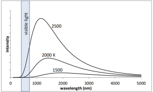
The characteristic spectrum of the emitted radiation depends on the temperature of the object. The spectrum of an ideal “blackbody” emitter is shown in the graphs below for three different (relatively high) temperatures. Notice that a hot body emits over a broad range of wavelengths. As the temperature of the object increases, the peak in the intensity spectrum moves to shorter wavelength and the power (proportional to the area under the curve) increases.

In this lab, the hot body is the filament of a small incandescent light bulb. The bulb will be heated by running current through it. By measuring the voltage across the bulb (V) and the current through it (I), you will be able to calculate the power radiated by the filament (P = IV) and the resistance of the filament (R = V/I). The temperature of the bulb can then be calculated from its resistance according to
[latex]T = 130.7 + 189.8 \left( \frac{R}{R_o}\right) - 1.327 \left( \frac{R}{R_o}\right)^2 \ \ (^\circ K)[/latex]
(where Ro is the room temperature resistance of the filament and K is showing the units in Kelvin.) You will then be able to examine the power emitted as a function of temperature.
Measurement Set #1 - Finding the Room Temperature Resistance
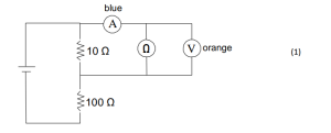
To measure the room temperature resistance of the bulb (Ω), you will need to use very small voltages (because if you heat up the bulb, it won’t be at room temperature!). This voltage divider circuit will help you control the power supply (instructions here) at small voltages. (Before attempting the actual measurement, omit the ammeter and the bulb, and connect the voltmeter directly across the 10 Ω resistor. Practice setting the power supply to small voltages, eg 10 mV, 20 mV.)

Measure the current near 5 mV, 10 mV, 15 mV, 20, 25, 30, 40, 50 … 90, 100 mV. (The values don’t have to be exact, but make sure you record the voltage and current at each point!) Calculate and plot the resistance as a function of voltage and extrapolate the curve to 0 V to find the room temperature resistance. (You don’t need to worry about calculating the uncertainties right now.)
Measurement Set #2 - Measuring Current at Higher Voltages
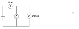
Once you have Ro, you can remove the voltage divider and connect the bulb directly across the power supply as below:

Measure the current at voltages of 0.1, 0.2, 0.3, 0.4, 0.5, 1, 2, 3, 4, 5, 9, 11, 13, 15 V. (Do not leave bulb lit too long at high voltages! The experiment is over if your bulb burns out...)
Congratulations on completing Lab 10!
Your post lab assignment is on the next page.
