2.1 – Bonding
Introduction
In chemistry, we discuss the properties of individual elements on the periodic table, as well as the molecules that are comprised of those elemental building blocks. Bonding allows for the association of individual atoms through the sharing of electrons and allows for the formation of molecules.
What is Bonding?
A chemical bond consists of a pair of electrons that are localized to certain regions of space between two nuclei. A bond is the result of the overlap of individual atomic orbitals, with the pair of electrons occupying the overlapping orbital space. Orbitals are regions around the nucleus of an atom where electrons are likely to be found. Chemical reactions result in bonds breaking and bond forming events, creating new molecules. Two atoms sharing one pair of electrons results a single covalent bond, while the sharing of two and three pairs of electrons create covalent double and triple bonds respectively.
Drawing Lewis Structures
This section provides a review of how to draw Lewis structures using a step-by-step approach, followed by an example of how to draw the Lewis structure of the bicarbonate anion, HCO3–.
Step-by-step approach to drawing Lewis structures:
- Count the total number of valence electrons, including charge of structure. Note that you need to add electrons if the species is negatively charged (an anion) and subtract electrons if the species is positively charged (a cation).
- Draw the skeletal structure, including the central and terminal atoms. Note that the least electronegative atom is usually the central atom, and hydrogen and fluorine are always terminal.
- Use the remaining electrons to complete the octet of all terminal atoms. Note that hydrogen needs only 2 electrons, not 8.
- Subtract all electrons used in previous steps and place any remaining electrons on the central atom. Sometimes this can lead to expanded octet where there are more than 8 electrons around an atom.
- Calculate formal charges (FC) on each atom, using the following formula:
FC = # of valence e– – # of bonds – # of nonbonding e– - Minimize formal charges by creating multiple bonds using nonbonding electrons. This typically happens when two neighboring atoms have opposite charges, one positive and the other negative.
- Ensure all atoms have an allowed electron count. Recall that C, N, O, F must obey octet rule, while others may have an expanded octet.
As an example, we will draw the Lewis structure of the bicarbonate anion, HCO3–, where C is the central atom, and H is bonded to O.
Step 1: Count the total number of valence electrons, including charge of structure
- We count 1 for hydrogen, 4 for carbon, 6 for each of the three oxygens, plus an additional 1 for the negative charge.
- Total number of valence electrons = 1 + 4 + 3(6) + 1 = 24 e–
Step 2: Draw the skeletal structure, including the central and terminal atoms (Figure 2.1.a). Note that C is the central atom, and H is bonded to O.

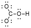
Step 3: Use the remaining electrons to complete the octet of all terminal atoms, or 2 e– for hydrogen (Figure 2.1.b). Note we are treating all the oxygen atoms as terminal (although one of the oxygen atoms is also a central atom, being attached to both carbon and hydrogen).
Step 4: Subtract all electrons used in previous steps and place any remaining electrons on the central atom.
- Number of electrons used so far: 8 lone pairs = 16 e–; 4 bonds = 8 e–
- Total = 16 + 8 = 24 e–
- All electrons have been accounted for, and none are left over for the central atom.
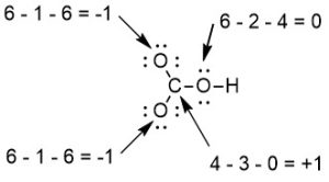
Step 5: Calculate formal charges (FC) on each atom (Figure 2.1.c). More information about formal charge and its utility can be found below in in the “Calculating Formal Charge” section. The formula for calculating formal charge is:
FC = # of valence electrons – # of bonds – # of lone electrons.
NOTE: We are subtracting the number of lone electrons, NOT the number of lone pairs. For example, if there is 1 lone pair, subtract 2 (since a lone pair has 2 electrons).
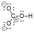
This Lewis structure can be drawn with all non-zero formal charges as shown in Figure 2.1.d:
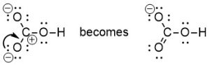
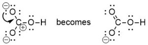
Step 6: Minimize formal charges by creating multiple bonds using nonbonding electrons.
To create a multiple bond, we use two neighbouring atoms, one of which has a positive formal charge while the other has a negative formal charge. A double bond is created when the lone pair of electrons (originally on oxygen) is shared between oxygen and carbon. We can use either one of the oxygen atoms on the left (both of which have a formal charge of -1), and the carbon atom (with a formal charge of +1). There are two choices of where to create a multiple bond, and therefore two resonance structures that can be drawn.
Using a lone pair of electrons from the bottom left oxygen to create a C=O double bond (Figure 2.1.e):
Using a lone pair of electrons from the top left oxygen to create a C=O double bond (Figure 2.1.f):
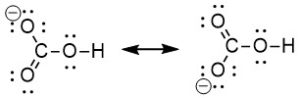
Both resonance structures drawn together in one diagram (Figure 2.1.g):
Step 7: Ensure all atoms have an allowed electron count. Recall that C, N, O, F must obey octet rule, while others may have an expanded octet.
The carbon and oxygen atoms have a complete octet, while hydrogen has two electrons.
Bond Polarity in Organic Chemistry
A covalent chemical bond represents the sharing of a pair of electrons by two nuclei. Although the electron density in a bond is found between two atoms, the electron density is often will biased towards one atom in the bond over the other. This creates a charge dipole between the 2 atoms in the bond, with one atom becoming electron rich and behaving as if it has a negative charge, and the other becoming electron poor and behaving as if it has a positive charge.
In organic chemistry, a C–C and C–H bond are considered non-polar. This is because the electronegativity differences are 0 and 0.4 respectively, so the electrons aren’t largely attracted to one atom over the other. This means that electron density resides more equally between these two atoms.
Any other C–X bond is considered polar, even if their electronegativities are similar. Here, the halogen (X) is more electronegative, and will pull electrons towards itself. Electron density will therefore reside closer to the halogen than to carbon. C–I is an example of a bond that you would expect to be non-polar due to the electronegativity difference of 0, but is considered polar. Electronegativity can help us predict bonding and reactivity, due to the preference of some atoms to carry electron density over others.
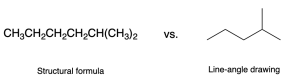
How To Draw Organic Molecules
Simple organic molecules like ethane are quick and straightforward to draw using a Lewis diagram, but for more complex molecules, drawing the Lewis structure will be tedious. Line-angle drawings (also called bond-line drawings), as in Figure 2.1.h, were therefore designed to efficiently draw organic molecules.
Line-angle representations are the most common way to depict organic molecules. There are several rules used to properly represent organic molecules using line-angle convention:
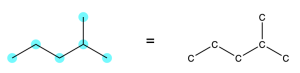
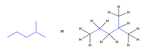
Rule 1: Every point or vertex in a line-angle diagram represents a carbon atom (Figure 2.1.i).
Rule 2: Assume that there are hydrogen atoms attached to each carbon for a valence of four (Figure 2.1.j).
Any carbon not shown to have four explicit bond has its valency implicitly filled with bonds to hydrogen atoms
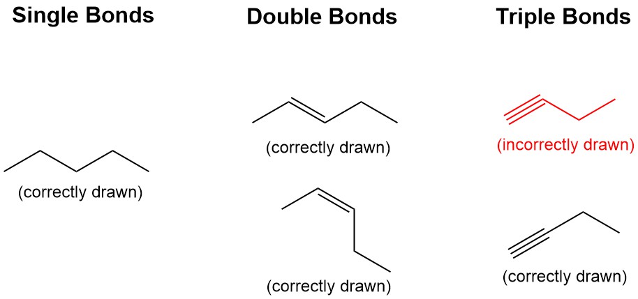
Rule 3: Draw molecules in a zig-zag shape for single/double blonds, and linear for triple bonds (Figure 2.1.k).
Line-angle convention is that the bonds angles mimic how the molecules are observed in 3 dimensional space. Alkanes and alkenes are observed to have a tetrahedral (109.5º) and trigonal planar (120 º) geometries respectively, which is closely represented by the zig-zag format. Alkynes are observed to have a liner geometry, and should be drawn in a linear format in line-angle.
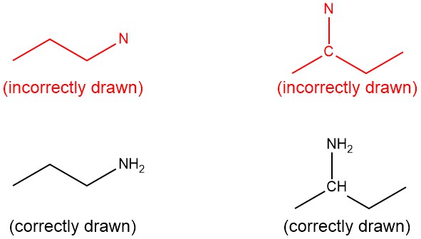
Rule 4: Any time you write the symbol for an atom (for heteroatoms and carbon), you MUST also write the hydrogens bound to that atom (Figure 2.1.l). Note: “heteroatom” means any atom that is not carbon or hydrogen.
It is important to remember that you do not need to indicate the hydrogens bonded to carbon if the carbon atom is not explicitly drawn. But if the carbon atom is explicitly drawn, you must show the bonded hydrogen atoms.
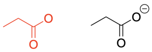
Rule 5: Indicate all non-zero formal charges with a (+) or (-) sign beside the atom carrying that charge (Figure 2.1.m).
A review of how to calculate formal charges is shown above, in the “Review of Lewis Structures” section of this chapter.
Rule 6: Count the carbon atoms and the substituents on each carbon atom. There are never more than 4 pairs of electrons on any second-row element.
Rule 7: Drawing lone pairs on all explicitly drawn atoms is optional (Figure 2.1.n). You can either draw all the lone pairs, only a select few of the lone pairs, or none of the lone pairs. You will see this come up in Chapter 3 – Reactivity.
Line–angle convention is utilized to emphasize the reactive parts of the molecule. For example, bonds between carbon and a heteroatom in a functional group are polar, and this is often the site of reactivity. In addition, positively or negatively charged species are often reactive. In contrast, bonds between carbon and hydrogen are generally non-polar and unreactive. Line-angle convention helps to de-emphasize the unreactive parts of molecules (by hiding hydrogen atoms and drawing carbon atoms as points or vertices), and emphasize the reactive parts of molecules (by explicitly showing heteroatoms and formal charges).
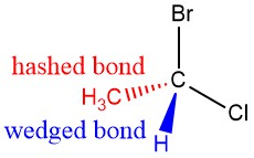
Are You Wondering? Wedged and Hashed Bonds
Recall that chemists indicate the 3D geometry of a molecule using wedged bonds and hashed bonds. A wedged bond indicates that the atom or group is pointing towards the viewer while a hashed bond indicates that the atom or group is pointing away from the viewer .
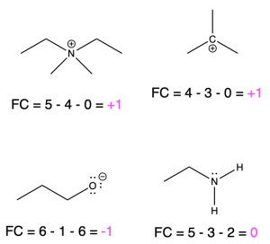
Formal Charge
A review of formal charge, and formula to calculate formal charge is provided above in the “Drawing Lewis Structures” section of this chapter. Formal charge is the charge assigned to atoms in molecules, and is a way of keeping track of electrons. On a line-angle representation of an organic molecule, both positive and negative formal charges must be indicated on the atom that bares the charge (as stated above in Rule 6). Positive and negative formal charges occur in a variety of organic molecules. A few examples are shown below, along with how to calculate the formal charge (Figure 2.1.o).
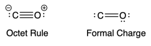
The Octet Rule
A source of stability for atoms is to have a complete shell of electrons in its outer shell. For second row elements like carbon, nitrogen, oxygen, we refer to it as the octet rule, since the outer shell can bear 8 electrons maximally. The octet rule will generally hold true for carbon, nitrogen, and oxygen. That is, they will typically have a complete octet. Having an atom with a complete octet is a larger stabilizing force than minimizing formal charges when drawing Lewis structures for second-row elements (C, N, O, F), as shown below for carbon monoxide, CO (Figure 2.1.p).
Trends in Formal Charge
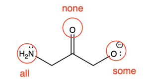
To determine the formal charge of any atom, we can use bonding patterns (which includes the number of lone pairs and bonds) for elements commonly found in organic chemistry. Below, we elaborate on bonding patterns and formal charges for oxygen, nitrogen, carbon and hydrogen.
For oxygen, nitrogen, and carbon, notice how the sum of the bonds and lone pairs never exceeds 4. This is due to the octet rule. Similarly, for hydrogen, notice how the sum of the bonds and lone pairs never exceeds 1.
Trends in Formal Charge for Oxygen
If oxygen is bonded to 1 atom and has 3 lone pairs, then it has a formal charge of -1 (Table 1, left). This is called an alkoxide, and it is similar to hydroxide, which shares the same bonding pattern.
If oxygen is bonded to 2 atoms and has 2 lone pairs, then it has a formal charge of zero (Table 1, center). An example is seen with the alcohol, ethanol. This is similar to water, which shares the same bonding pattern.
If oxygen is bonded to 3 atoms and has 1 lone pair, then it has a formal charge of +1 (Table 1, right). This is called an oxonium, and it is similar to hydronium, which shares the same bonding pattern.
Table 1. Bonding patterns for oxygen, with formal charge calculations.
| Negative | Neutral | Positive |
Alkoxide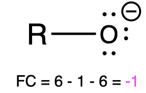 |
Alcohol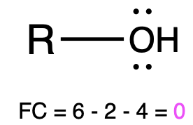 |
Oxonium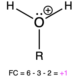 |
Hydroxide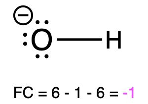 |
Water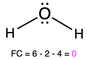 |
Hydronium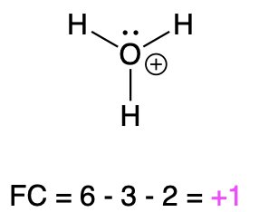 |
Trends in Formal Charge for Nitrogen
If nitrogen is bonded to 2 atoms and has 2 lone pairs, then it has a formal charge of –1 (Table 2, left). An example is seen with amide.
If nitrogen is bonded to 3 atoms and has 1 lone pair, then it has a formal charge of zero (Table 2, center). An example is seen with ammonia.
If nitrogen is bonded to 4 atoms and has no lone pairs, then it has a formal charge of +1 (Table 2, right). An example is seen with the ammonium ion.
Table 2. Bonding patterns for nitrogen, with formal charge calculations.
| Negative | Neutral | Positive |
Amide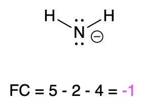 |
Ammonia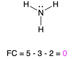 |
Ammonium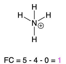 |
Dimethylamide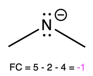 |
Ethanamine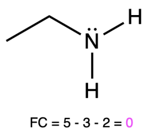 |
Ethanaminium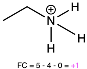 |
Trends in Formal Charge for Carbon
If carbon is bonded to 3 atoms and 1 lone pair, then it has a formal charge of –1 (Table 3, left). An example is seen with a negatively charged carbanion.
If carbon is bonded to 4 atoms and no lone pairs, then it has a formal charge of zero (Table 3, center). An example is seen with propane.
If carbon is bonded to 3 atoms and no lone pairs, then it has a formal charge of +1 (Table 3, right). An example is seen with a positively charged carbocation.
Table 3. Bonding patterns for carbon, with formal charge calculations.
| Negative | Neutral | Positive |
Carbanion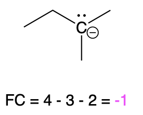 |
Propane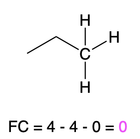 |
Carbocation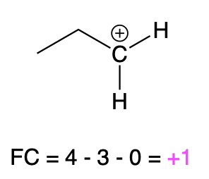 |
Trends in Formal Charge for Hydrogen
If hydrogen carries a lone pair of electrons, then it has a formal charge of is –1 (Table 4, left). This is called a hydride. You will see hydride used as a reactant in Chapter 3.4.
If hydrogen does not carry a lone pair of electrons and instead is covalently bonded to another atom of equal, or higher electronegativity, it is sharing its one electron, and carries a formal charge of 0 (Table 4, center). An example is hydrogen gas (H2). You will see hydrogen gas used as a reactant in Chapter 3.2.
If hydrogen does not carry any electrons, then the charge of the atom is +1. This is called a proton, because its positive charge comes from the one proton inside the nucleus. You will see a proton used as a reactant (in the form of an acid) in several reactions in Chapter 3.
Table 4. Bonding patterns for hydrogen, with formal charge calculations.
| Negative | Neutral | Positive |
Hydride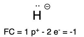 |
Hydrogen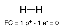 |
Proton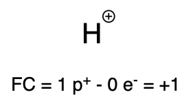 |
Key Takeaways
- Chemistry involves studying elements on the periodic table and how they form molecules through bonding.
- Chemical bonding involves the sharing of electrons between atoms to create molecules.
- Covalent bonds can be single, double, or triple, based on the number of shared electron pairs.
- Bond polarity depends on electronegativity differences, affecting electron distribution.
- Line-angle drawings are used to represent organic molecules efficiently.
- Rules for line-angle drawings include representing carbon atoms at vertices, assuming hydrogen atoms attached to carbon, and drawing bond angles based on geometry.
- Formal charge helps track electrons in molecules and is calculated using valence electrons, bonds, and lone electrons.
- The octet rule states that atoms aim for a complete outer shell with 8 electrons.
- Trends in formal charge are determined for oxygen, nitrogen, carbon, and hydrogen
Diversity in Chemistry: Dorothy Hodgkin
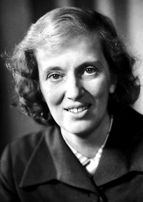
Throughout this chapter, we draw the structures of various compounds using line-angle drawing, but how exactly did scientists deduce these structures? There are many techniques nowadays that can be used to elucidate the structures of both small and large molecules, with one of them being X-ray crystallography. This technique involves shooting a beam of x-rays at a solid crystal, which causes the rays to diffract, bending the light in various directions. The angles and extent of diffraction can then be measured to determine the density of electrons around the crystal, which is used to deduce how the atoms are arranged in the crystal. Dorothy Hodgkin was a renowned X-ray crystallographer, using the technique to determine the exact structure of many complex, yet significant compounds, such as penicillin and insulin. During her Ph.D experience, Hodgkin was diagnosed with rheumatoid arthritis in her hands, presenting itself as an obstacle in her work; however, she persevered and continued to work despite being unable to operate simple switches, opting to make long levers that she could use instead. In 1964, Hodgkin was recognized for her work, being the sole receiver of the Nobel Prize in Chemistry for her X-ray crystallography studies and continued to travel around the world to give presentations on her work despite her condition. More information on Hodgkin and her scientific career can be found on her page on The Royal Society website.
The result of the overlap of individual atomic orbitals, with the pair of electrons occupying the overlapping orbital space
A bond where the two atoms share a pair of electrons between the two nuclei.
A covalent bond where the electron density resides equally between the two atoms, as the electrons aren’t largely attracted to one atom over the other.
A covalent in which the electron density is more biased towards one atom over the other. This is because one atom is more electronegative than the other, pulling electrons towards itself.
The charge assigned to atoms in molecules to keep track of electrons.
The tendency of atoms to prefer to have eight electrons in the valence shell to increase its stability. This rule generally holds true for second row elements such as C, N, and O.
