Problems & Exercises
Problems & Exercises
7.2 The Second Condition for Equilibrium
- (a) When opening a door, you push on it perpendicularly with a force of 55.0 N at a distance of 0.850m from the hinges. What torque are you exerting relative to the hinges? (b) Does it matter if you push at the same height as the hinges?
- When tightening a bolt, you push perpendicularly on a wrench with a force of 165 N at a distance of 0.140 m from the center of the bolt. (a) How much torque are you exerting in newton × meters (relative to the center of the bolt)? (b) Convert this torque to footpounds.
- Two children push on opposite sides of a door during play. Both push horizontally and perpendicular to the door. One child pushes with a force of 17.5 N at a distance of 0.600 m from the hinges, and the second child pushes at a distance of 0.450 m. What force must the second child exert to keep the door from moving? Assume friction is negligible.
- Use the second condition for equilibrium [latex](\text{net }\tau\text{ }=\text{ 0})[/latex] to calculate [latex]F_{\text{p}}[/latex] in Example 7.1, employing any data given or solved for in part (a) of the example.
- Repeat the seesaw problem in Example 7.1 with the center of mass of the seesaw 0.160 m to the left of the pivot (on the side of the lighter child) and assuming a mass of 12.0 kg for the seesaw. The other data given in the example remain unchanged. Explicitly show how you follow the steps in the Problem-Solving Strategy for static equilibrium.
7.3 Stability
- Suppose a horse leans against a wall as in Figure 7.29, emulating a scene in the comedy movie Cat Ballou. Calculate the force exerted on the wall assuming that force is horizontal while using the data in the schematic representation of the situation. Note that the force exerted on the wall is equal in magnitude and opposite in direction to the force exerted on the horse, keeping it in equilibrium. The total mass of the horse and rider is 500 kg. Take the data to be accurate to three digits.
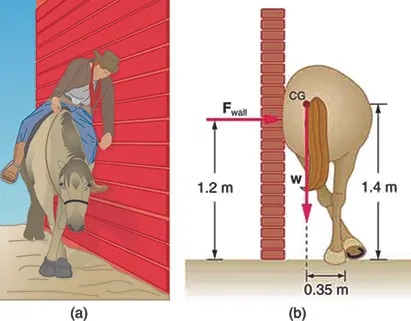
Figure 7.29 Image from OpenStax College Physics 2e, CC-BY 4.0
Image Description
The image is a composite of two illustrations labeled as (a) and (b).
Illustration (a) depicts a person riding a horse near a tall vertical red wall. The person is leaning to the left, away from the horse, with one hand resting on the wall for balance.
Illustration (b) is a side view diagram of a horse against a wall. It includes measurements and forces labeled on the diagram. The horse’s back is against a brick wall, and the tail is shown in detail. The vertical distance from the ground to the top of the horse is marked as 1.2 meters, indicating the height of the wall. Another line indicates the height of the horse’s center of gravity (CG) at 1.4 meters. A force labeled “Fwall” is acting horizontally on the horse at the height of the wall. A downward force, “w,” indicates the weight of the horse, acting from the center of gravity. The horizontal distance from the CG to the horse’s hind leg is labeled as 0.35 meters.
- Two children of mass 20.0 kg and 30.0 kg sit balanced on a seesaw with the pivot point located at the center of the seesaw. If the children are separated by a distance of 3.00 m, at what distance from the pivot point is the small child sitting in order to maintain the balance?
- (a) Calculate the magnitude and direction of the force on each foot of the horse in Figure 7.29 (two are on the ground), assuming the center of mass of the horse is midway between the feet. The total mass of the horse and rider is 500kg. (b) What is the minimum coefficient of friction between the hooves and ground? Note that the force exerted by the wall is horizontal.
- A person carries a plank of wood 2.00 m long with one hand pushing down on it at one end with a force [latex]\text{F}_{1}[/latex] and the other hand holding it up at .500 m from the end of the plank with force [latex]\text{F}_{2}[/latex]. If the plank has a mass of 20.0 kg and its center of gravity is at the middle of the plank, what are the magnitudes of the forces [latex]\text{F}_{1}[/latex] and [latex]\text{F}_{2}[/latex]?
- A 17.0-m-high and 11.0-m-long wall under construction and its bracing are shown in Figure 7.30. The wall is in stable equilibrium without the bracing but can pivot at its base. Calculate the force exerted by each of the 10 braces if a strong wind exerts a horizontal force of 650 N on each square meter of the wall. Assume that the net force from the wind acts at a height halfway up the wall and that all braces exert equal forces parallel to their lengths. Neglect the thickness of the wall.
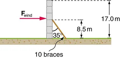
Figure 7.30 Image from OpenStax College Physics 2e, CC-BY 4.0
Image Description
The image is a diagram illustrating the stabilization of a vertical wall structure against wind force. The wall is shown on the left side with a force labeled “Fwind” represented by an arrow pointing from left to right, indicating the direction of the wind force. A diagonal brace is positioned against the wall at an angle of 35 degrees. This brace runs from the base of the wall to the ground. The total height of the wall is marked as 17.0 meters. The point where the brace makes contact with the wall is labeled, showing it is 8.5 meters above the ground. The ground is depicted as a horizontal green line with the label “10 braces” beneath it, indicating the number of braces used.
- (a) What force must be exerted by the wind to support a 2.50-kg chicken in the position shown in Figure 9.31? (b) What is the ratio of this force to the chicken’s weight? (c) Does this support the contention that the chicken has a relatively stable construction?
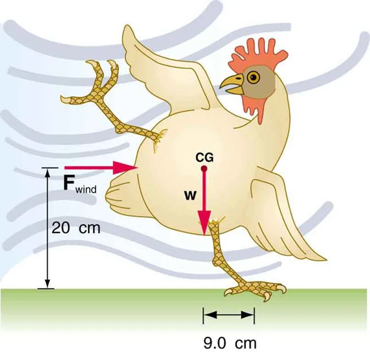
Figure 7.31 Image from OpenStax College Physics 2e, CC-BY 4.0
Image Description
The image is a diagram illustrating the physics of a chicken experiencing forces while standing on one leg. The chicken is depicted with one leg raised and the other firmly on the ground. The diagram includes several labeled elements:
- Fwind: A red horizontal arrow pointing to the left, representing the force of the wind acting on the chicken. The arrow is labeled with “Fwind” and is positioned at a height of 20 centimeters above the ground.
- W: A red vertical arrow pointing downward from the chicken’s body, labeled “W” to represent the weight of the chicken.
- CG: A point labeled “CG” (Center of Gravity) indicating the chicken’s center of mass located slightly above the leg that is on the ground.
- Measurements: The distance from the ground to the position of the “Fwind” arrow is noted as 20 centimeters. The horizontal distance from the chicken’s standing leg to a point directly below the center of gravity is labeled as 9.0 centimeters.
The background displays dynamic, wavy lines symbolizing the wind. The chicken is oriented to the right, with its wings spread slightly for balance.
- Suppose the weight of the drawbridge in Figure 7.32 is supported entirely by its hinges and the opposite shore, so that its cables are slack. The mass of the bridge is 2500 kg. (a) What fraction of the weight is supported by the opposite shore if the point of support is directly beneath the cable attachments? (b) What is the direction and magnitude of the force the hinges exert on the bridge under these circumstances?
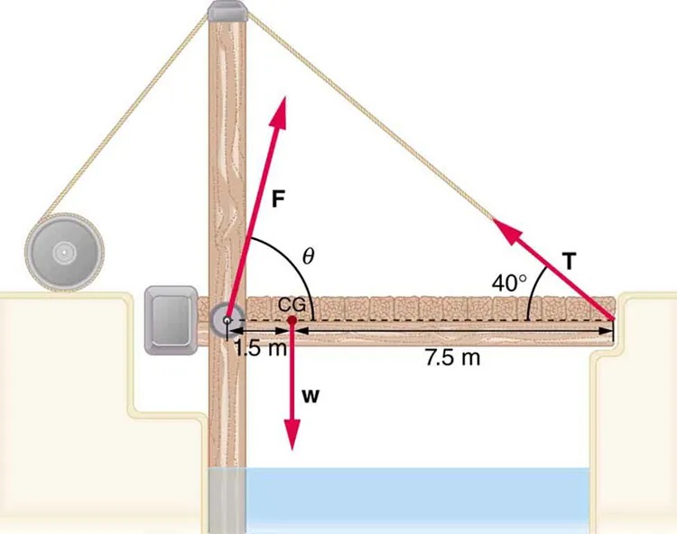
Figure 7.32 A small drawbridge, showing the forces on the hinges ([latex]\text{F}[/latex]), its weight ([latex]\text{w}[/latex]), and the tension in its wires Image from OpenStax College Physics 2e, CC-BY 4.0
Image Description
The image illustrates a mechanical setup involving a bridge-like structure, a vertical beam, a pulley system, and vectors representing forces and angles. Here’s a detailed description:
- A vertical beam is situated close to the edge of a water body.
- An extended horizontal platform or bridge is attached to the beam and stretches across the water, measuring 7.5 meters in length from the base of the beam.
- The center of gravity (CG) of the bridge is depicted, situated 1.5 meters from the beam.
- Three main force vectors are illustrated:
- Vector w is pointing downward from the center of gravity, representing the weight.
- Vector T originates from the endpoint of the bridge and is angled upwards at 40 degrees from the horizontal, representing tension.
- Vector F is positioned at the base of the beam and angled upward, indicating a force applied at an angle θ.
- A pulley is mounted at the top of the beam, connecting to T via a rope.
- Suppose a 900-kg car is on the bridge in Figure 7.32 with its center of mass halfway between the hinges and the cable attachments. (The bridge is supported by the cables and hinges only.) (a) Find the force in the cables. (b) Find the direction and magnitude of the force exerted by the hinges on the bridge.
- A sandwich board advertising sign is constructed as shown in Figure 7.33. The sign’s mass is 8.00 kg. (a) Calculate the tension in the chain assuming no friction between the legs and the sidewalk. (b) What force is exerted by each side on the hinge?
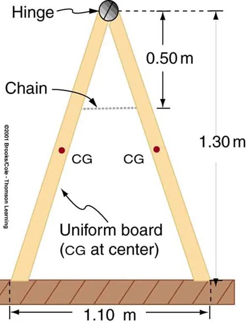
Figure 7.33 A sandwich board advertising sign demonstrates tension. Image from OpenStax College Physics 2e, CC-BY 4.0
Image Description
The image depicts a diagram of a structure resembling an inverted V or an A-frame, supported by a horizontal base. The following components and measurements are noted:
- Two symmetrical boards are shown, joined at the top by a circular hinge.
- A chain is connected near the top of the left board, providing stability.
- The distance from the hinge to the horizontal base is marked as 1.30 meters.
- The distance from the hinge to the chain is marked as 0.50 meters.
- The base of the structure, where the boards meet the horizontal element, measures 1.10 meters wide.
- Each board has a point marked “CG” (center of gravity) indicating that the boards are uniform in weight distribution.
- The label “Uniform board (CG at center)” accompanies the boards, indicating uniformity in design.
- (a) What minimum coefficient of friction is needed between the legs and the ground to keep the sign in Figure 7.33 in the position shown if the chain breaks? (b) What force is exerted by each side on the hinge?
- An athlete is attempting to perform splits. From the information given in Figure 7.34, calculate the magnitude and direction of the force exerted on each foot by the floor.
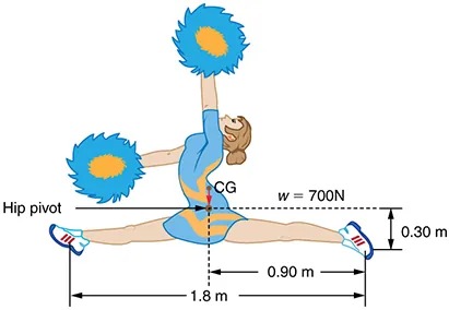
Figure 7.34 An athlete performs full split. The center of gravity and the various distances from it are shown. Image from OpenStax College Physics 2e, CC-BY 4.0
Image Description
The image is an illustration of a cheerleader performing a split leap. The cheerleader is shown in mid-air with both legs extended horizontally, each adorned with a sneaker. She holds large pom-poms in each hand, raised above her head. The body is slightly arched back in a dynamic pose.
Measurements and labels in the diagram indicate specific dimensions and forces:
- The distance from the left foot to the hip pivot is 1.8 meters.
- The distance from the hip pivot to the right foot is 0.9 meters.
- The vertical distance from the hip pivot to the ground level is 0.3 meters.
- The label ‘CG’ indicates the center of gravity near the cheerleader’s waist.
- The symbol ‘w = 700N’ represents the weight, indicating a force of 700 Newtons.
7.4 Applications of Statics, Including Problem-Solving Strategies
- To get up on the roof, a person (mass 70.0 kg) places a 6.00-m aluminum ladder (mass 10.0 kg) against the house on a concrete pad with the base of the ladder 2.00 m from the house. The ladder rests against a plastic rain gutter, which we can assume to be frictionless. The center of mass of the ladder is 2 m from the bottom. The person is standing 3 m from the bottom. What are the magnitudes of the forces on the ladder at the top and bottom?
- In Figure 7.20, the cg of the pole held by the pole vaulter is 2.00 m from the left hand, and the hands are 0.700 m apart. Calculate the force exerted by (a) his right hand and (b) his left hand. (c) If each hand supports half the weight of the pole in Figure 7.18, show that the second condition for equilibrium [latex](\text{net} \tau = \text{0})[/latex] is satisfied for a pivot other than the one located at the center of gravity of the pole. Explicitly show how you follow the steps in the Problem-Solving Strategy for static equilibrium described above.
7.5 Simple Machines
- What is the mechanical advantage of a nail puller—similar to the one shown in Figure 7.21 —where you exert a force [latex]\text{45 cm}[/latex] from the pivot and the nail is [latex]\text{1}.\text{8 cm}[/latex] on the other side? What minimum force must you exert to apply a force of [latex]\text{1250 N}[/latex] to the nail?
- Suppose you needed to raise a 250-kg mower a distance of 6.0 cm above the ground to change a tire. If you had a 2.0-m long lever, where would you place the fulcrum if your force was limited to 300 N?
- a) What is the mechanical advantage of a wheelbarrow, such as the one in Figure 7.22, if the center of gravity of the wheelbarrow and its load has a perpendicular lever arm of 5.50 cm, while the hands have a perpendicular lever arm of 1.02 m? (b) What upward force should you exert to support the wheelbarrow and its load if their combined mass is 55.0 kg? (c) What force does the wheel exert on the ground?
- A typical car has an axle with [latex]1 . \text{10 cm}[/latex] radius driving a tire with a radius of [latex]\text{27} .\text{5 cm}[/latex]. What is its mechanical advantage assuming the very simplified model in Figure 7.23(b)?
- What force does the nail puller in Exercise 7.19 exert on the supporting surface? The nail puller has a mass of 2.10 kg.
- If you used an ideal pulley of the type shown in Figure 7.24(a) to support a car engine of mass [latex]\text{115 kg}[/latex], (a) What would be the tension in the rope? (b) What force must the ceiling supply, assuming you pull straight down on the rope? Neglect the pulley system’s mass.
- Repeat Exercise 7.24 for the pulley shown in Figure 7.24(c), assuming you pull straight up on the rope. The pulley system’s mass is [latex]\text{7}.\text{00 kg}[/latex].
7.6 Forces and Torques in Muscles and Joints
- Verify that the force in the elbow joint in Example 7.4 is 407 N, as stated in the text.
- Two muscles in the back of the leg pull on the Achilles tendon as shown in Figure 7.35. What total force do they exert?
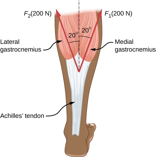
Figure 7.35 The Achilles tendon of the posterior leg serves to attach plantaris, gastrocnemius, and soleus muscles to calcaneus bone. Image from OpenStax College Physics 2e, CC-BY 4.0
Image Description
The image is a diagram illustrating the anatomy of the lower leg, specifically focusing on the muscles and tendons at the back of the leg. It shows:
– Two main muscles labeled as “Lateral gastrocnemius” and “Medial gastrocnemius.” These muscles are represented as rounded, pinkish areas on either side of the leg, positioned to show symmetry.
– Each muscle is pulling with a force of 200 N (Newtons) as indicated by the arrows pointing upward and labeled as “F₂(200 N)” for the lateral side and “F₁(200 N)” for the medial side.
– The arrows form an angle of 20 degrees with a central vertical dashed line that runs down the center of the leg.
– The “Achilles’ tendon” is shown as a white structure below the muscles, attaching them to the heel. It converges from the two muscles creating a V-shaped junction.
– The angles and forces suggest a biomechanical explanation of how the muscles and tendons work together to exert force on the Achilles’ tendon and enable movement, such as walking or running.
- The upper leg muscle (quadriceps) exerts a force of 1250 N, which is carried by a tendon over the kneecap (the patella) at the angles shown in Figure 7.36. Find the direction and magnitude of the force exerted by the kneecap on the upper leg bone (the femur).
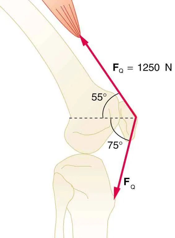
Figure 7.36 The knee joint works like a hinge to bend and straighten the lower leg. It permits a person to sit, stand, and pivot. Image from OpenStax College Physics 2e, CC-BY 4.0
Image Description
The image is a diagram of a human knee joint illustrating the forces and angles involved in a biomechanical context. It displays:
– A representation of the femur and tibia, the two bones forming the knee joint, along with muscle fibers above the knee.
– Two angles marked at the joint:
– One angle measuring 55 degrees.
– Another angle measuring 75 degrees.
– A red arrow representing force, labeled as \( F_Q \).
– The magnitude of the force \( F_Q \) is given as 1250 Newtons, shown as \( F_Q = 1250 \, \text{N} \).
The diagram is likely used to study or demonstrate mechanical or muscular forces related to the knee joint.
- A device for exercising the upper leg muscle is shown in Figure 7.37, together with a schematic representation of an equivalent lever system. Calculate the force exerted by the upper leg muscle to lift the mass at a constant speed. Explicitly show how you follow the steps in the Problem-Solving Strategy for static equilibrium in 7.4 Applications of Statics, Including Problem-Solving Strategies.
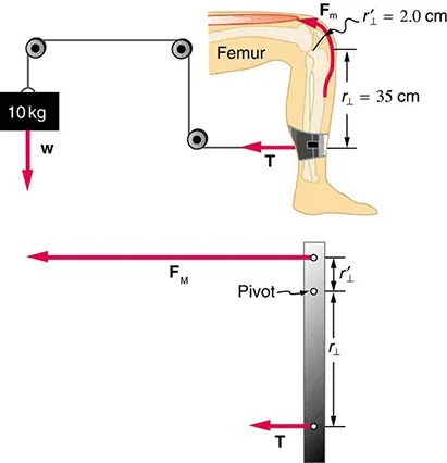
Figure 7.37 A mass is connected by pulleys and wires to the ankle in this exercise device. Image from OpenStax College Physics 2e, CC-BY 4.0
Image Description
The image consists of two diagrams illustrating the mechanics of lifting a weight using a leg, specifically focusing on the forces involved.
Upper Diagram:
- Shows the side view of a human leg bent at the knee.
- A muscle force (Fm) is acting upwards on the femur.
- The femur is labeled, and the muscle connects to it, forming an angle with the leg.
- Two distances are marked: r’1 = 2.0 cm from the muscle to the pivot, and r1 = 35 cm from the pivot to where the force T acts on the lower leg.
- A weight of 10 kg is being lifted, generating a downward force labeled w.
Lower Diagram:
- Shows a simplified representation of the leg and forces.
- A horizontal bar represents the leg with a pivot point marked.
- The force FM is shown acting horizontally, while the tension T acts on the opposite side of the pivot.
- Distances are marked similar to the upper diagram: r’1 and r1.
The diagrams illustrate the principles of levers and moments, demonstrating how muscle forces are used to lift weights through the mechanics of the leg. The forces and distances are critical in understanding the torque generated in this system.
- A person working at a drafting board may hold her head as shown in Figure 7.38, requiring muscle action to support the head. The three major acting forces are shown. Calculate the direction and magnitude of the force supplied by the upper vertebrae [latex]\textbf{F}_{\text{V}}[/latex] to hold the head stationary, assuming that this force acts along a line through the center of mass as do the weight and muscle force.
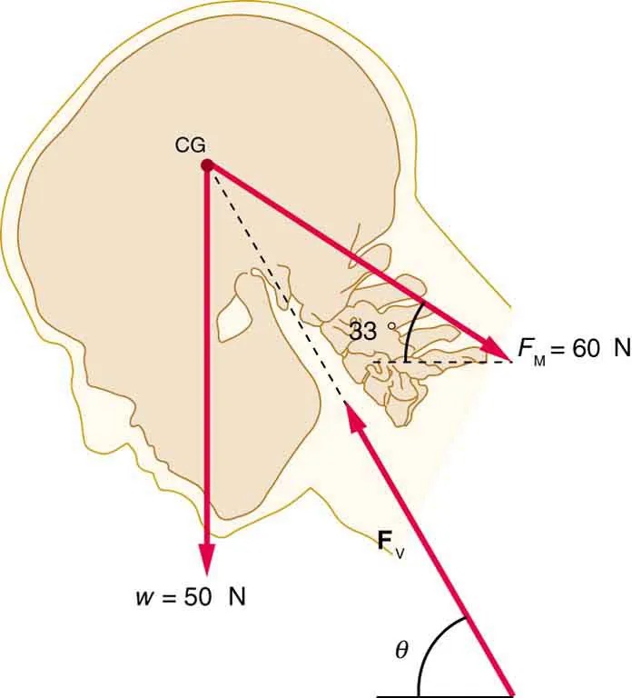
Figure 7.38 Image from OpenStax College Physics 2e, CC-BY 4.0
Image Description
This image is a diagram of a human head in profile, illustrating forces acting on it. The head is shown in a beige outline with some internal anatomy visible. Three red arrows represent different forces.
- The first arrow, labeled “CG,” points vertically downwards, representing the center of gravity with a force of w = 50 N.
- The second arrow, labeled “FM,” points diagonally from the back of the head forward, indicating a force of FM = 60 N.
- The third arrow, labeled “FV,” points diagonally downward and forward. The diagram includes a dashed line connecting these forces, forming an angle inside the head.
An angle of 33 degrees is marked between the horizontal dashed line and the direction of the force FM. Another angle, labeled as theta (θ), is marked below the force FV arrow.
- We analyzed the biceps muscle example with the angle between forearm and upper arm set at [latex]\text{90}º[/latex]. Using the same numbers as in Example 7.4, find the force exerted by the biceps muscle when the angle is [latex]\text{120}º[/latex] and the forearm is in a downward position.
- Even when the head is held erect, as in Figure 7.39, its center of mass is not directly over the principal point of support (the atlanto-occipital joint). The muscles at the back of the neck should therefore exert a force to keep the head erect. That is why your head falls forward when you fall asleep in the class. (a) Calculate the force exerted by these muscles using the information in the figure. (b) What is the force exerted by the pivot on the head?
-
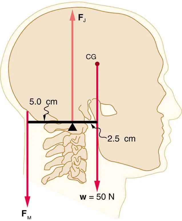
Figure 7.39 The center of mass of the head lies in front of its major point of support, requiring muscle action to hold the head erect. A simplified lever system is shown. Image from OpenStax College Physics 2e, CC-BY 4.0
Image Description
The image depicts a sagittal section of a human head focusing on the biomechanics, specifically the forces acting on the skull and neck. It illustrates forces, weights, and measurements with arrows and annotations.
- The head is shown in profile, displaying the skull, neck vertebrae, and associated measurements.
- Two vertical arrows, labeled FM and FJ, indicate forces acting on the head and neck.
- The arrow FM points upwards at the back, representing muscle force.
- The arrow FJ points downwards at the front, representing joint force.
- Another arrow pointing downwards is labeled with the weight w = 50 N, showing the gravitational force acting through the center of gravity (CG).
- A horizontal line is used to measure distances: 5.0 cm from FM to the fulcrum (pivot point), and 2.5 cm from the fulcrum to the CG point.
- The vertebrae in the neck are shown with anatomical accuracy to depict where forces are applied.
- A 75-kg man stands on his toes by exerting an upward force through the Achilles tendon, as in Figure 9.40. (a) What is the force in the Achilles tendon if he stands on one foot? (b) Calculate the force at the pivot of the simplified lever system shown—that force is representative of forces in the ankle joint.
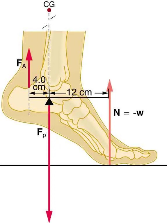
Figure 7.40 The muscles in the back of the leg pull the Achilles tendon when one stands on one’s toes. A simplified lever system is shown. Image from OpenStax College Physics 2e, CC-BY 4.0
Image Description
This image illustrates a biomechanical diagram of a human foot. The foot is shown in a side view with bones visible. Several forces and measurements are indicated:
- Force labeled as FA is directed upwards from the heel.
- Force labeled as FP points downward through the point identified as the center of gravity (CG) above the heel.
- There is an indication of a reaction force labeled N and equal to -w (weight), directed upwards near the toes.
Measurements are provided on the foot:
- Distance of 4.0 cm from the heel to where the vertical force CG is applied.
- Distance of 12 cm from the heel to the point where the opposing force N is applied.
Arrows and labels provide visual indicators of the direction and location of the forces acting on the foot.
- A father lifts his child as shown in Figure 7.41. What force should the upper leg muscle exert to lift the child at a constant speed?
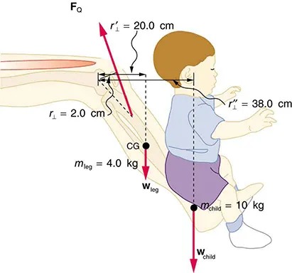
Figure 7.41 A child being lifted by a father’s lower leg. Image from OpenStax College Physics 2e, CC-BY 4.0
Image Description
The image is a diagram illustrating the forces and measurements involved when a person holds a child on their leg. The diagram depicts a side view of a child’s body seated on an adult’s leg. Various forces and measurements are labeled throughout the diagram:
- An arrow labeled FQ points upward from near the hip area.
- The upper leg is shown, along with an arrow for mleg = 4.0 kg directed downward, representing the weight of the leg.
- Two horizontal distances from the hip joint are marked: r⊥ = 2.0 cm and r’1 = 20.0 cm, both with arrows indicating measurement directions.
- The child is sitting at the edge of the adult’s knee, with an arrow labeled wchild, pointing downward, representing the child’s weight.
- The child’s weight is given as wchild = 10 kg.
- A vertical measurement from the hip to the child’s center of mass indicates r’1 = 38.0 cm.
- The child’s torso is illustrated, with lines marking wleg and wchild at the locations corresponding to their respective centers of gravity (CG).
This diagram illustrates the physics of balancing a child on an adult’s knee, including vectors and measurements of force and mass positioning. It serves as a visual aid for understanding torques and forces in a practical scenario.
- Unlike most of the other muscles in our bodies, the masseter muscle in the jaw, as illustrated in Figure 7.42, is attached relatively far from the joint, enabling large forces to be exerted by the back teeth. (a) Using the information in the figure, calculate the force exerted by the lower teeth on the bullet. (b) Calculate the force on the joint.
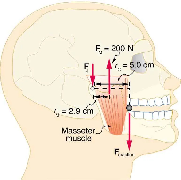
Figure 7.42 A person clenching a bullet between his teeth. Image from OpenStax College Physics 2e, CC-BY 4.0
Image Description
The image is a diagram of a human skull in profile, focusing on the jaw and surrounding muscles. It highlights the forces acting on the jaw with specific labels and arrows.
- The Masseter muscle is depicted in red, showing its position on the side of the jaw.
- Two radii are labeled: rM with a length of 2.9 cm, and rC with a length of 5.0 cm.
- A force FM is marked as 200 N and shows an upward arrow from the bottom of the masseter muscle.
- A force FJ is indicated with a downward arrow near the top of the jaw.
- A downward force labeled FReaction is shown at the point where the jaw connects.
The diagram is meant to illustrate the biomechanical forces involved in the jaw’s movement, particularly focusing on the masseter muscle’s contribution to closing the jaw.
- Integrated Concepts: Suppose we replace the 4.0-kg book in Exercise 7.31 of the biceps muscle with an elastic exercise rope that obeys Hooke’s Law. Assume its force constant [latex]k = \text{600} \text{N}/\text{m}[/latex]. (a) How much is the rope stretched (past equilibrium) to provide the same force [latex]F_{\text{B}}[/latex] as in this example? Assume the rope is held in the hand at the same location as the book. (b) What force is on the biceps muscle if the exercise rope is pulled straight up so that the forearm makes an angle of [latex]\text{25}º[/latex] with the horizontal? Assume the biceps muscle is still perpendicular to the forearm.
- (a) What force should the woman in Figure 7.43 exert on the floor with each hand to do a push-up? Assume that she moves up at a constant speed. (b) The triceps muscle at the back of her upper arm has an effective lever arm of 1.75 cm, and she exerts force on the floor at a horizontal distance of 20.0 cm from the elbow joint. Calculate the magnitude of the force in each triceps muscle, and compare it to her weight. (c) How much work does she do if her center of mass rises 0.240 m? (d) What is her useful power output if she does 25 pushups in one minute?
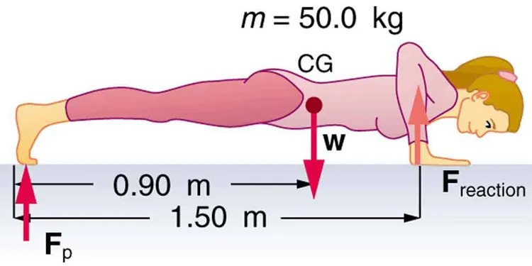
Figure 7.43 A woman doing pushups. Image from OpenStax College Physics 2e, CC-BY 4.0
Image Description
The image depicts a person in a plank position with a focus on physics concepts related to forces and equilibrium. The person, dressed in a pink outfit, lies horizontally facing downwards, supported by their forearms and toes. Several annotations and symbols are included to illustrate the physics involved:
- The mass of the person is labeled as “m = 50.0 kg”.
- The center of gravity (labeled as “CG”) is marked on the person’s body with a dot and a downward arrow labeled “w”, representing the weight force.
- A horizontal line extends from the feet to the forearms, marked with distances: “0.90 m” from the feet to the center of gravity and “1.50 m” from the center of gravity to the forearms.
- A vertical arrow labeled “Fp” points upwards from the feet, indicating a force acting at the feet.
- Another vertical arrow labeled “Freaction” points upwards from the forearms, representing a reaction force.
- You have just planted a sturdy 2-m-tall palm tree in your front lawn for your mother’s birthday. Your brother kicks a 500 g ball, which hits the top of the tree at a speed of 5 m/s and stays in contact with it for 10 ms. The ball falls to the ground near the base of the tree and the recoil of the tree is minimal. (a) What is the force on the tree? (b) The length of the sturdy section of the root is only 20 cm. Furthermore, the soil around the roots is loose and we can assume that an effective force is applied at the tip of the 20 cm length. What is the effective force exerted by the end of the tip of the root to keep the tree from toppling? Assume the tree will be uprooted rather than bend. (c) What could you have done to ensure that the tree does not uproot easily?
- Unreasonable Results: Suppose two children are using a uniform seesaw that is 3.00 m long and has its center of mass over the pivot. The first child has a mass of 30.0 kg and sits 1.40 m from the pivot. (a) Calculate where the second 18.0 kg child must sit to balance the seesaw. (b) What is unreasonable about the result? (c) Which premise is unreasonable, or which premises are inconsistent?
- Construct Your Own Problem: Consider a method for measuring the mass of a person’s arm in anatomical studies. The subject lies on her back, extends her relaxed arm to the side and two scales are placed below the arm. One is placed under the elbow and the other under the back of her hand. Construct a problem in which you calculate the mass of the arm and find its center of mass based on the scale readings and the distances of the scales from the shoulder joint. You must include a free body diagram of the arm to direct the analysis. Consider changing the position of the scale under the hand to provide more information, if needed. You may wish to consult references to obtain reasonable mass values.
“Problems & Exercises” from College Physics 2e by OpenStax is licensed under a Creative Commons Attribution 4.0 International License.
