9.5 Pascal’s Principle
Learning Objectives
By the end of this section, you will be able to:
- Define pressure.
- State Pascal’s principle.
- Understand applications of Pascal’s principle.
- Derive relationships between forces in a hydraulic system.
Pressure is defined as force per unit area. Can pressure be increased in a fluid by pushing directly on the fluid? Yes, but it is much easier if the fluid is enclosed. The heart, for example, increases blood pressure by pushing directly on the blood in an enclosed system (valves closed in a chamber). If you try to push on a fluid in an open system, such as a river, the fluid flows away. An enclosed fluid cannot flow away, and so pressure is more easily increased by an applied force.
What happens to a pressure in an enclosed fluid? Since atoms in a fluid are free to move about, they transmit the pressure to all parts of the fluid and to the walls of the container. Remarkably, the pressure is transmitted undiminished. This phenomenon is called Pascal’s principle, because it was first clearly stated by the French philosopher and scientist Blaise Pascal (1623–1662): A change in pressure applied to an enclosed fluid is transmitted undiminished to all portions of the fluid and to the walls of its container.
Pascal’s Principle
A change in pressure applied to an enclosed fluid is transmitted undiminished to all portions of the fluid and to the walls of its container.
Pascal’s principle, an experimentally verified fact, is what makes pressure so important in fluids. Since a change in pressure is transmitted undiminished in an enclosed fluid, we often know more about pressure than other physical quantities in fluids. Moreover, Pascal’s principle implies that the total pressure in a fluid is the sum of the pressures from different sources. We shall find this fact—that pressures add—very useful.
Blaise Pascal had an interesting life in that he was home-schooled by his father who removed all of the mathematics textbooks from his house and forbade him to study mathematics until the age of 15. This, of course, raised the boy’s curiosity, and by the age of 12, he started to teach himself geometry. Despite this early deprivation, Pascal went on to make major contributions in the mathematical fields of probability theory, number theory, and geometry. He is also well known for being the inventor of the first mechanical digital calculator, in addition to his contributions in the field of fluid statics.
Application of Pascal’s Principle
One of the most important technological applications of Pascal’s principle is found in a hydraulic system, which is an enclosed fluid system used to exert forces. The most common hydraulic systems are those that operate car brakes. Let us first consider the simple hydraulic system shown in Figure 9.11.
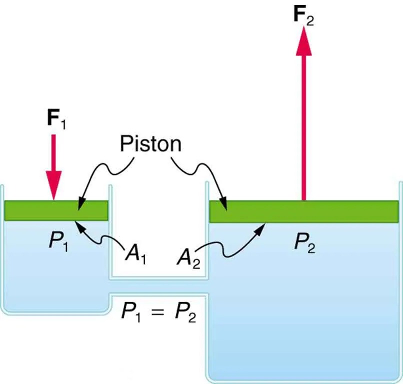
Figure 9.11 A typical hydraulic system with two fluid-filled cylinders, capped with pistons and connected by a tube called a hydraulic line. A downward force [latex]\textbf{F}_{1}[/latex] on the left piston creates a pressure that is transmitted undiminished to all parts of the enclosed fluid. This results in an upward force [latex]\textbf{F}_{2}[/latex] on the right piston that is larger than [latex]\textbf{F}_{1}[/latex] because the right piston has a larger area. Image from OpenStax College Physics 2e, CC-BY 4.0
Image Description
The image depicts a cross-section of a hydraulic system illustrating Pascal’s Principle. There are two connected chambers filled with fluid. Each chamber has a piston on top, represented by green rectangles.
The left chamber shows a force labeled “F1” with an arrow pointing downwards onto the piston with the area labeled “A1”. The pressure in this chamber is labeled “P1”.
The right chamber shows a force labeled “F2” with an arrow pointing upwards from the piston with the area labeled “A2”. The pressure here is labeled “P2”.
The equation “P1 = P2” indicates the principle that pressure is equal throughout the fluid system. Arrows indicate the flow and equalization of pressure from one chamber to the other.
Relationship Between Forces in a Hydraulic System
We can derive a relationship between the forces in the simple hydraulic system shown in Figure 9.11 by applying Pascal’s principle. Note first that the two pistons in the system are at the same height, and so there will be no difference in pressure due to a difference in depth. Now the pressure due to [latex]F_{1}[/latex] acting on area [latex]A_{1}[/latex] is simply [latex]P_{1} = \frac{F_{1}}{A_{1}}[/latex], as defined by [latex]P = \frac{F}{A}[/latex]. According to Pascal’s principle, this pressure is transmitted undiminished throughout the fluid and to all walls of the container. Thus, a pressure [latex]P_{2}[/latex] is felt at the other piston that is equal to [latex]P_{1}[/latex]. That is [latex]P_{1} = P_{2}[/latex].
But since [latex]P_{2} = \frac{F_{2}}{A_{2}}[/latex], we see that [latex]\frac{F_{1}}{A_{1}} = \frac{F_{2}}{A_{2}}[/latex].
This equation relates the ratios of force to area in any hydraulic system, providing the pistons are at the same vertical height and that friction in the system is negligible. Hydraulic systems can increase or decrease the force applied to them. To make the force larger, the pressure is applied to a larger area. For example, if a 100-N force is applied to the left cylinder in Figure 9.11 and the right one has an area five times greater, then the force out is 500 N. Hydraulic systems are analogous to simple levers, but they have the advantage that pressure can be sent through tortuously curved lines to several places at once.
Example 9.6
Calculating Force of Wheel Cylinders: Pascal Puts on the Brakes
Consider the automobile hydraulic system shown in Figure 9.12.
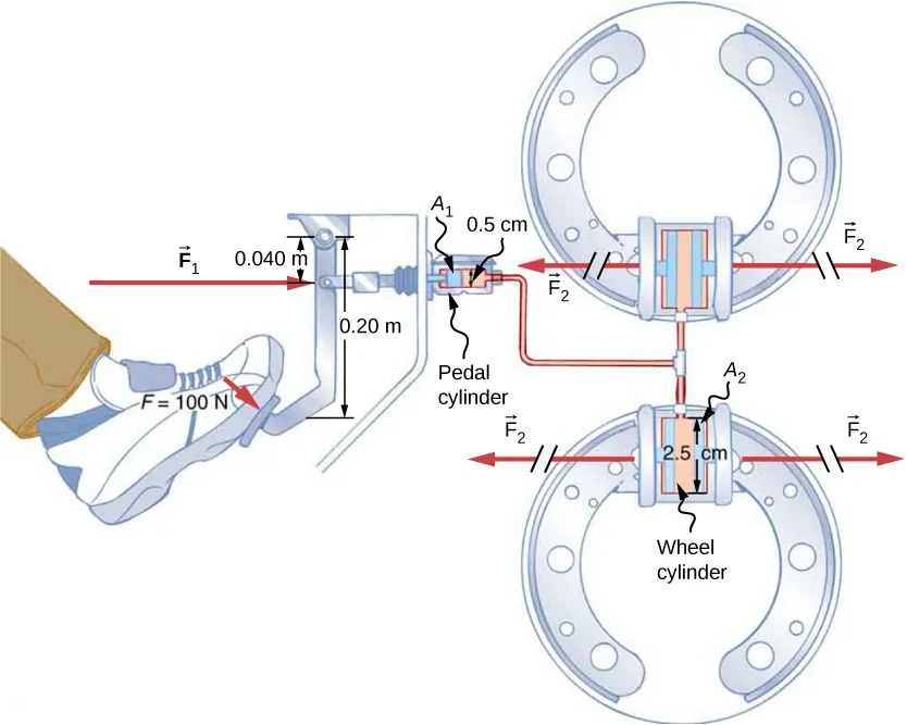
Figure 9.12 Hydraulic brakes use Pascal’s principle. The driver exerts a force of 100 N on the brake pedal. This force is increased by the simple lever and again by the hydraulic system. Each of the identical wheel cylinders receives the same pressure and, therefore, creates the same force output [latex]F_{2}[/latex]. The circular cross-sectional areas of the pedal and wheel cylinders are represented by [latex]A_{1}[/latex] and [latex]A_{2}[/latex], respectively Image from OpenStax College Physics 2e, CC-BY 4.0
Image Description
The image depicts a hydraulic braking system in operation. On the left side of the image, a foot is pressing down on a brake pedal, applying a force of F = 100 N. This force is represented by a red arrow labeled F1, pointing to the right. A lever mechanism is shown, where the distance from the pedal to the pivot point is marked as 0.20 meters, and the distance from the pivot to the hydraulic connection is 0.040 meters.
The force F1 is transmitted through a pedal cylinder with a cross-sectional area of A1 = 0.5 cm. A line connects this pedal cylinder to a wheel cylinder. The wheel cylinder has a larger cross-sectional area of A2 = 2.5 cm and is positioned near two drums, each of which represents a wheel brake.
Force from the pedal cylinder is converted and applied as force F2 (also represented by red arrows) at the wheel brakes. The image illustrates how the hydraulic system amplifies the force applied by the foot to increase the braking power on the wheels.
A force of 100 N is applied to the brake pedal, which acts on the pedal cylinder through a lever. A force of 500 N is exerted on the pedal cylinder. (The reader can verify that the force is 500 N using techniques of statics from 7.4 Applications of Statics, Including Problem-Solving Strategies.) Pressure created in the pedal cylinder is transmitted to four wheel cylinders. The pedal cylinder has a diameter of 0.500 cm, and each wheel cylinder has a diameter of 2.50 cm. Calculate the force [latex]F_{2}[/latex] created at each of the wheel cylinders.
Strategy
We are given the force [latex]F_{1}[/latex] that is applied to the pedal cylinder. The cross-sectional areas [latex]A_{1}[/latex] and [latex]A_{2}[/latex] can be calculated from their given diameters. Then [latex]\frac{F_{1}}{A_{1}} = \frac{F_{2}}{A_{2}}[/latex] can be used to find the force [latex]F_{2}[/latex]. Manipulate this algebraically to get [latex]F_{2}[/latex] on one side and substitute known values:
Solution
Pascal’s principle applied to hydraulic systems is given by [latex]\frac{F_{1}}{A_{1}} = \frac{F_{2}}{A_{2}}[/latex]:
[latex]\begin{align*}F_{2} &= \frac{A_{2}}{A_{1}} \\[2ex] F_{1} &= \frac{πr_{2}^{2}}{πr_{1}^{2}} \\ &= \frac{\left(1.25 cm\right)^{2}}{\left(0.250 cm\right)^{2}} \times \text{500 N} \\ &= 1 . \text{25} \times \text{10}^{4} \text{N} .\end{align*}[/latex]
Discussion
This value is the force exerted by each of the four wheel cylinders. Note that we can add as many wheel cylinders as we wish. If each has a 2.50-cm diameter, each will exert [latex]1 . \text{25} \times \text{10}^{4} \text{N} .[/latex]
A simple hydraulic system, such as a simple machine, can increase force but cannot do more work than done on it. Work is force times distance moved, and the wheel cylinder moves through a smaller distance than the pedal cylinder. Furthermore, the more wheels added, the smaller the distance each moves. Many hydraulic systems—such as power brakes and those in bulldozers—have a motorized pump that actually does most of the work in the system. The movement of the legs of a spider is achieved partly by hydraulics. Using hydraulics, a jumping spider can create a force that makes it capable of jumping 25 times its length!
Making Connections: Conservation of Energy
Conservation of energy applied to a hydraulic system tells us that the system cannot do more work than is done on it. Work transfers energy, and so the work output cannot exceed the work input. Power brakes and other similar hydraulic systems use pumps to supply extra energy when needed.
