8.3 Dynamics of Rotational Motion: Rotational Inertia
Learning Objectives
By the end of this section, you will be able to:
- Understand the relationship between force, mass and acceleration.
- Study the turning effect of force.
- Study the analogy between force and torque, mass and moment of inertia, and linear acceleration and angular acceleration.
If you have ever spun a bike wheel or pushed a merry-go-round, you know that force is needed to change angular velocity as seen in Figure 10.9. In fact, your intuition is reliable in predicting many of the factors that are involved. For example, we know that a door opens slowly if we push too close to its hinges. Furthermore, we know that the more massive the door, the more slowly it opens. The first example implies that the farther the force is applied from the pivot, the greater the angular acceleration; another implication is that angular acceleration is inversely proportional to mass. These relationships should seem very similar to the familiar relationships among force, mass, and acceleration embodied in Newton’s second law of motion. There are, in fact, precise rotational analogs to both force and mass.
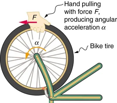
Figure 8.9 Force is required to spin the bike wheel. The greater the force, the greater the angular acceleration produced. The more massive the wheel, the smaller the angular acceleration. If you push on a spoke closer to the axle, the angular acceleration will be smaller. Image from OpenStax College Physics 2e, CC-BY 4.0
Image Description
The image depicts a diagram of a bicycle wheel with a force applied to it. A hand is shown pulling the wheel with a labeled force, F, in the direction indicated by an arrow. This action produces an angular acceleration, represented by the symbol α, indicated by a curved arrow along the inside of the wheel. The wheel is labeled as a “Bike tire.” The hand applying the force is located at the top of the wheel, pulling horizontally. The angular acceleration arrow is shown moving counterclockwise. Overall, the diagram illustrates the concept of how an applied force generates angular acceleration in a wheel.
To develop the precise relationship among force, mass, radius, and angular acceleration, consider what happens if we exert a force [latex]F[/latex] on a point mass [latex]m[/latex] that is at a distance [latex]r[/latex] from a pivot point, as shown in Figure 8.10. Because the force is perpendicular to [latex]r[/latex], an acceleration [latex]a = \frac{F}{m}[/latex] is obtained in the direction of [latex]F[/latex]. We can rearrange this equation such that [latex]F = \text{ma}[/latex] and then look for ways to relate this expression to expressions for rotational quantities. We note that [latex]a = rα[/latex], and we substitute this expression into [latex]F = \text{ma}[/latex], yielding
[latex]F = \text{mr} \alpha .[/latex]
Recall that torque is the turning effectiveness of a force. In this case, because [latex]\textbf{F}[/latex] is perpendicular to [latex]r[/latex], torque is simply [latex]\tau = Fr[/latex]. So, if we multiply both sides of the equation above by [latex]r[/latex], we get torque on the left-hand side. That is,
[latex]\text{rF} = \text{mr}^{2} \alpha[/latex]
or
[latex]\tau = \text{mr}^{2} α.[/latex]
This last equation is the rotational analog of Newton’s second law ([latex]F = \text{ma}[/latex]), where torque is analogous to force, angular acceleration is analogous to translational acceleration, and [latex]\text{mr}^{2}[/latex] is analogous to mass (or inertia). The quantity [latex]\text{mr}^{2}[/latex] is called the rotational inertia or moment of inertia of a point mass [latex]m[/latex] a distance [latex]r[/latex] from the center of rotation.
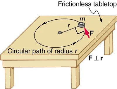
Figure 8.10 An object is supported by a horizontal frictionless table and is attached to a pivot point by a cord that supplies centripetal force. A force [latex]F[/latex] is applied to the object perpendicular to the radius [latex]r[/latex], causing it to accelerate about the pivot point. The force is kept perpendicular to [latex]r[/latex]. Image from OpenStax College Physics 2e, CC-BY 4.0
Image Description
The image depicts a diagram of an object moving in a circular path on a frictionless tabletop. There is a table with a circular path drawn on its surface, labeled as having a radius ‘r’. A small object with mass ‘m’ is shown on the circular path. An arrow labeled ‘F’ represents the force acting on the object, pointing towards the center of the circle. The force ‘F’ is perpendicular to the radius ‘r’, as indicated by another label. Overall, the diagram illustrates the concept of centripetal force required to maintain an object in uniform circular motion on a frictionless surface.
Making Connections: Rotational Motion Dynamics
Dynamics for rotational motion is completely analogous to linear or translational dynamics. Dynamics is concerned with force and mass and their effects on motion. For rotational motion, we will find direct analogs to force and mass that behave just as we would expect from our earlier experiences.
Rotational Inertia and Moment of Inertia
Before we can consider the rotation of anything other than a point mass like the one in Figure 8.10, we must extend the idea of rotational inertia to all types of objects. To expand our concept of rotational inertia, we define the moment of inertia
[latex]I[/latex] of an object to be the sum of [latex]\text{mr}^{2}[/latex] for all the point masses of which it is composed. That is, [latex]I = \sum \text{mr}^{2}[/latex]. Here [latex]I[/latex] is analogous to [latex]m[/latex] in translational motion. Because of the distance [latex]r[/latex], the moment of inertia for any object depends on the chosen axis. Actually, calculating [latex]I[/latex] is beyond the scope of this text except for one simple case—that of a hoop, which has all its mass at the same distance from its axis.
A hoop’s moment of inertia around its axis is therefore [latex]\text{MR}^{2}[/latex], where [latex]M[/latex] is its total mass and [latex]R[/latex] its radius. (We use [latex]M[/latex] and [latex]R[/latex] for an entire object to distinguish them from [latex]m[/latex] and [latex]r[/latex] for point masses.) In all other cases, we must consult Figure 8.11 (note that the table is piece of artwork that has shapes as well as formulae) for formulas for [latex]I[/latex] that have been derived from integration over the continuous body. Note that [latex]I[/latex] has units of mass multiplied by distance squared ([latex]\text{kg} \cdot \text{m}^{2}[/latex]), as we might expect from its definition.
The general relationship among torque, moment of inertia, and angular acceleration is
[latex]\text{net }\tau = Iα[/latex]
or
[latex]\alpha = \frac{\text{net }\tau}{I} ,[/latex]
where net [latex]\tau[/latex] is the total torque from all forces relative to a chosen axis. For simplicity, we will only consider torques exerted by forces in the plane of the rotation. Such torques are either positive or negative and add like ordinary numbers. The relationship in [latex]\tau = Iα , \alpha = \frac{\text{net }\tau}{I}[/latex] is the rotational analog to Newton’s second law and is very generally applicable. This equation is actually valid for any torque, applied to any object, relative to any axis.
As we might expect, the larger the torque is, the larger the angular acceleration is. For example, the harder a child pushes on a merry-go-round, the faster it accelerates. Furthermore, the more massive a merry-go-round, the slower it accelerates for the same torque. The basic relationship between moment of inertia and angular acceleration is that the larger the moment of inertia, the smaller is the angular acceleration. But there is an additional twist. The moment of inertia depends not only on the mass of an object, but also on its distribution of mass relative to the axis around which it rotates. For example, it will be much easier to accelerate a merry-go-round full of children if they stand close to its axis than if they all stand at the outer edge. The mass is the same in both cases, but the moment of inertia is much larger when the children are at the edge.
Take-Home Experiment
Cut out a circle that has about a 10 cm radius from stiff cardboard. Near the edge of the circle, write numbers 1 to 12 like hours on a clock face. Position the circle so that it can rotate freely about a horizontal axis through its center, like a wheel. (You could loosely nail the circle to a wall.) Hold the circle stationary and with the number 12 positioned at the top, attach a lump of blue putty (sticky material used for fixing posters to walls) at the number 3. How large does the lump need to be to just rotate the circle? Describe how you can change the moment of inertia of the circle. How does this change affect the amount of blue putty needed at the number 3 to just rotate the circle? Change the circle’s moment of inertia and then try rotating the circle by using different amounts of blue putty. Repeat this process several times.
Problem-Solving Strategy for Rotational Dynamics
- Examine the situation to determine that torque and mass are involved in the rotation. Draw a careful sketch of the situation.
- Determine the system of interest.
- Draw a free body diagram. That is, draw and label all external forces acting on the system of interest.
- Apply [latex]net τ = Iα , \alpha = \frac{\text{net }\tau}{I}[/latex], the rotational equivalent of Newton’s second law, to solve the problem. Care must be taken to use the correct moment of inertia and to consider the torque about the point of rotation.
- As always, check the solution to see if it is reasonable.
Making Connections
In statics, the net torque is zero, and there is no angular acceleration. In rotational motion, net torque is the cause of angular acceleration, exactly as in Newton’s second law of motion for rotation.
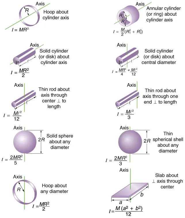
Figure 8.11 Some rotational inertias. Image from OpenStax College Physics 2e, CC-BY 4.0
Image Description
This image displays diagrams of various geometric objects with their respective moments of inertia, each in relation to an axis. The objects and their moments of inertia are described as follows:
| Object | Moment of Inertia (I) | Description |
|---|---|---|
| Hoop about cylinder axis | I = MR2 | A circular hoop with the axis along the center line of the hoop. |
| Annular cylinder (or ring) about cylinder axis | I = (M/2)(R12 + R22) | A hollow cylinder with two radii, the axis along the center line. |
| Solid cylinder (or disk) about cylinder axis | I = (MR2)/2 | A full solid cylinder or disk rotating about its central axis. |
| Solid cylinder (or disk) about central diameter | I = (MR2)/4 + (Ml2)/12 | A solid cylinder or disk with rotation about its central diameter. |
| Thin rod about axis through center ⊥ to length | I = (Ml2)/12 | A thin rod rotating about an axis perpendicular to its length through the center. |
| Thin rod about axis through one end ⊥ to length | I = (Ml2)/3 | A thin rod with rotation about an axis at one end, perpendicular to its length. |
| Solid sphere about any diameter | I = (2MR2)/5 | A solid sphere rotating about any diameter. |
| Thin spherical shell about any diameter | I = (2MR2)/3 | A thin spherical shell rotating about any diameter. |
| Hoop about any diameter | I = (MR2)/2 | A hoop rotating about any of its diameters. |
| Slab about axis through center | I = M(a2 + b2)/12 | A rectangular slab with rotation about an axis through its center. |
Example 8.7
Calculating the Effect of Mass Distribution on a Merry-Go-Round
Consider the father pushing a playground merry-go-round in Figure 8.12. He exerts a force of 250 N at the edge of the 50.0-kg merry-go-round, which has a 1.50 m radius. Calculate the angular acceleration produced (a) when no one is on the merry-go-round and (b) when an 18.0-kg child sits 1.25 m away from the center. Consider the merry-go-round itself to be a uniform disk with negligible retarding friction.
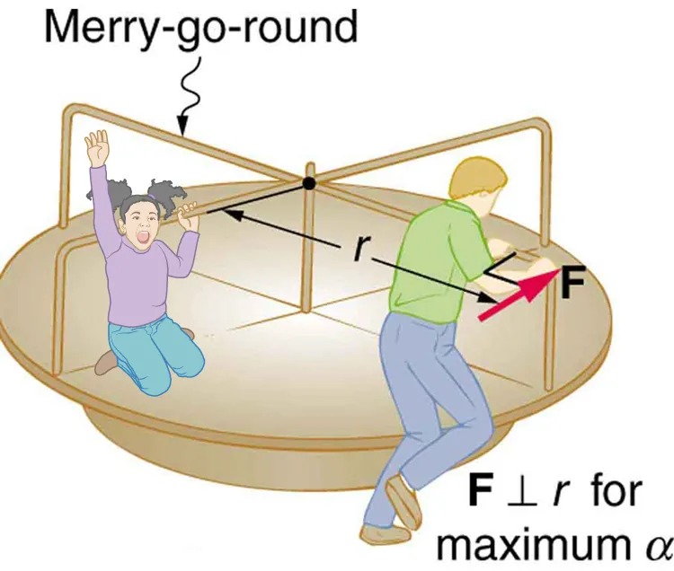
Figure 8.12 A father pushes a playground merry-go-round at its edge and perpendicular to its radius to achieve maximum torque. Image from OpenStax College Physics 2e, CC-BY 4.0
Image Description
The image shows a diagram of a merry-go-round. A person is standing on the edge, pushing the structure, depicted by an arrow labeled “F” indicating the force. An arrow perpendicular to “r” is drawn from the center towards the person, labeled “F ⊥ r for maximum α,” suggesting the direction of application for optimal angular acceleration. A child is on their knees inside the merry-go-round with raised arms, appearing to enjoy the ride. The merry-go-round is circular with vertical bars and a central pivot point. The force is demonstrated to be applied tangentially for effectiveness in rotation.
Strategy
Angular acceleration is given directly by the expression [latex]\alpha = \frac{\text{net }\tau}{I}[/latex]:
[latex]\alpha = \frac{\tau}{I} .[/latex]
To solve for [latex]\alpha[/latex], we must first calculate the torque [latex]\tau[/latex] (which is the same in both cases) and moment of inertia [latex]I[/latex] (which is greater in the second case). To find the torque, we note that the applied force is perpendicular to the radius and friction is negligible, so that
[latex]\tau = rF \text{sin }\theta = \left(\right. \text{1}.\text{50 m} \left.\right) \left(\right. \text{250 N} \left.\right) = \text{375 N} \cdot \text{m}.[/latex]
Solution for (a)
The moment of inertia of a solid disk about this axis is given in Figure 8.11 to be
[latex]\frac{1}{2} \text{MR}^{2} ,[/latex]
where [latex]M = \text{50}.\text{0 kg}[/latex] and [latex]R = \text{1}.\text{50 m}[/latex], so that
[latex]\begin{align*}I &= (0 . 500) \left(\right. \text{50}.\text{0 kg} \left.\right) \left(\right. \text{1}.\text{50 m} \left.\right)^{2}\\ &= \text{56}.\text{25 kg} \cdot \text{m}^{2} .\end{align*}[/latex]
Now, after we substitute the known values, we find the angular acceleration to be
[latex]\alpha = \frac{\tau}{I} = \frac{\text{375 N} \cdot \text{m}}{\text{56}.\text{25 kg} \cdot \text{m}^{2}} = \text{6}.\text{67} \frac{\text{rad}}{\text{s}^{2}} .[/latex]
Solution for (b)
We expect the angular acceleration for the system to be less in this part, because the moment of inertia is greater when the child is on the merry-go-round. To find the total moment of inertia [latex]I[/latex], we first find the child’s moment of inertia [latex]I_{\text{c}}[/latex] by considering the child to be equivalent to a point mass at a distance of 1.25 m from the axis. Then,
[latex]\begin{align*}I_{\text{c}} &= MR^{2}\\ &= \left(\right. \text{18}.\text{0 kg} \left.\right) \left(\right. \text{1}.\text{25 m} \left.\right)^{2}\\ &= \text{28}.\text{13 kg} \cdot \text{m}^{2} .\end{align*}[/latex]
The total moment of inertia is the sum of moments of inertia of the merry-go-round and the child (about the same axis). To justify this sum to yourself, examine the definition of [latex]I[/latex]:
[latex]\begin{align*}I &= \text{28}.\text{13 kg} \cdot \text{m}^{2} + \text{56}.\text{25 kg} \cdot \text{m}^{2}\\ &= \text{84}.\text{38 kg} \cdot \text{m}^{2} .\end{align*}[/latex]
Substituting known values into the equation for [latex]\alpha[/latex] gives
[latex]\alpha = \frac{\tau}{I} = \frac{\text{375 N} \cdot \text{m}}{\text{84}.\text{38 kg} \cdot \text{m}^{2}} = \text{4}.\text{44} \frac{\text{rad}}{\text{s}^{2}} .[/latex]
Discussion
The angular acceleration is less when the child is on the merry-go-round than when the merry-go-round is empty, as expected. The angular accelerations found are quite large, partly due to the fact that friction was considered to be negligible. If, for example, the father kept pushing perpendicularly for 2.00 s, he would give the merry-go-round an angular velocity of 13.3 rad/s when it is empty but only 8.89 rad/s when the child is on it. In terms of revolutions per second, these angular velocities are 2.12 rev/s and 1.41 rev/s, respectively. The father would end up running at about 50 km/h in the first case. Summer Olympics, here he comes! Confirmation of these numbers is left as an exercise for the reader.
Check Your Understanding
Torque is the analog of force and moment of inertia is the analog of mass. Force and mass are physical quantities that depend on only one factor. For example, mass is related solely to the numbers of atoms of various types in an object. Are torque and moment of inertia similarly simple?
Click for Solution
Solution
No. Torque depends on three factors: force magnitude, force direction, and point of application. Moment of inertia depends on both mass and its distribution relative to the axis of rotation. So, while the analogies are precise, these rotational quantities depend on more factors.
