3.5 Addition of Velocities
Learning Objectives
By the end of this section, you will be able to:
- Apply principles of vector addition to determine relative velocity.
- Explain the significance of the observer in the measurement of velocity.
Relative Velocity
If a person rows a boat across a rapidly flowing river and tries to head directly for the other shore, the boat instead moves diagonally relative to the shore, as in Figure 3.40. The boat does not move in the direction in which it is pointed. The reason, of course, is that the river carries the boat downstream. Similarly, if a small airplane flies overhead in a strong crosswind, you can sometimes see that the plane is not moving in the direction in which it is pointed, as illustrated in Figure 3.41. The plane is moving straight ahead relative to the air, but the movement of the air mass relative to the ground carries it sideways.
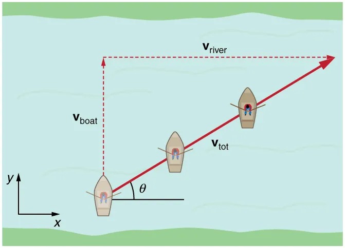
Figure 3.40 A boat trying to head straight across a river will actually move diagonally relative to the shore as shown. Its total velocity (solid arrow) relative to the shore is the sum of its velocity relative to the river plus the velocity of the river relative to the shore. Image from OpenStax College Physics 2e, CC-BY 4.0
Image Description
The image depicts a diagram of a boat navigating a river. The background shows a blue river bordered by green banks at the top and bottom. There are three boats depicted along a diagonal path across the river.
Here are the elements illustrated in the diagram:
- There is a labeled vboat vector shown as a dashed red arrow pointing upwards from the first boat, indicating the boat’s velocity relative to the water.
- A vriver vector is also present, shown as a horizontal dashed red arrow indicating the velocity of the river.
- A resultant velocity vector, labeled vtot, is drawn as a solid red arrow extending diagonally from the first boat, passing through the subsequent boats, indicating the total velocity of the boat as it moves across the river.
- An angle θ is marked between the vboat vector and the horizontal line, demonstrating the angle at which the boat is heading relative to the riverbank.
In the bottom-left corner, there is an x and y axis that indicates the coordinate system for the river flow direction.
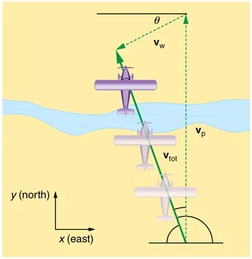
Figure 3.41 An airplane heading straight north is instead carried to the west and slowed down by wind. The plane does not move relative to the ground in the direction it points; rather, it moves in the direction of its total velocity Image from OpenStax College Physics 2e, CC-BY 4.0
Image Description
The image depicts a diagram used to illustrate the vector addition of velocities in physics. It features three planes shown at different positions over a water body, indicating the path of motion.
– A river is shown running horizontally across the image, colored in light blue.
– Three airplanes are depicted, representing different stages of motion, starting from the bottom and ascending diagonally to the top left.
– A green arrow labeled vtot shows the total velocity of the airplane relative to the ground.
– A vertical green arrow labeled vw depicts the velocity component of wind, which is directed north.
– A slanted arrow labeled vp represents the airplane’s velocity relative to the air.
– An angle θ is formed between the total velocity vector and the wind’s velocity vector, illustrating the angle of drift.
– At the bottom left of the image, a coordinate axis shows the directions: y (north) and x (east).
The diagram aims to explain how the resultant velocity is affected by both wind and the plane’s velocity.
In each of these situations, an object has a velocity relative to a medium (such as a river) and that medium has a velocity relative to an observer on solid ground. The velocity of the object relative to the observer is the sum of these velocity vectors, as indicated in Figure 3.40 and Figure 3.41. These situations are only two of many in which it is useful to add velocities. In this module, we first re-examine how to add velocities and then consider certain aspects of what relative velocity means.
How do we add velocities? Velocity is a vector (it has both magnitude and direction); the rules of vector addition discussed in 3.2 Vector Addition and Subtraction: Graphical Methods and 3.3 Vector Addition and Subtraction: Analytical Methods apply to the addition of velocities, just as they do for any other vectors. In one-dimensional motion, the addition of velocities is simple—they add like ordinary numbers. For example, if a field hockey player is moving at [latex]\text{5}\textrm{ }\text{m}/\text{s}[/latex] straight toward the goal and drives the ball in the same direction with a velocity of [latex]\text{30}\textrm{ }\text{m}/\text{s}[/latex] relative to her body, then the velocity of the ball is [latex]\text{35}\textrm{ }\text{m}/\text{s}[/latex] relative to the stationary, profusely sweating goalkeeper standing in front of the goal.
In two-dimensional motion, either graphical or analytical techniques can be used to add velocities. We will concentrate on analytical techniques. The following equations give the relationships between the magnitude and direction of velocity ([latex]v[/latex] and [latex]\theta[/latex]) and its components ([latex]v_{x}[/latex] and [latex]v_{y}[/latex]) along the x– and y-axes of an appropriately chosen coordinate system:
[latex]v_{x} = v \text{cos} \theta[/latex]
[latex]v_{y} = v \text{sin} \theta[/latex]
[latex]v = \sqrt{v_{x}^{2} + v_{y}^{2}}[/latex]
[latex]\theta = \text{tan}^{- 1} \left(\right. v_{y} / v_{x} \left.\right) .[/latex]
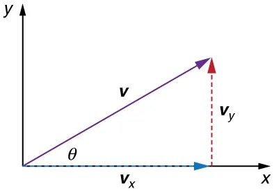
Figure 3.42 The velocity, [latex]v[/latex], of an object traveling at an angle [latex]\theta[/latex] to the horizontal axis is the sum of component vectors [latex]\textbf{v}_{x}[/latex] and [latex]\textbf{v}_{y}[/latex]. Image from OpenStax College Physics 2e, CC-BY 4.0
Image Description
The image is a diagram depicting a vector on a two-dimensional Cartesian coordinate system. Here’s a description of its components:
– The horizontal axis is labeled x, and the vertical axis is labeled y.
– There is a vector v represented by a purple arrow, extending from the origin toward the first quadrant.
– The vector v forms an angle θ with the horizontal axis, which is marked as a diagonal line extending from the origin.
– The horizontal component of the vector, labeled vx, is shown as a blue arrow on the x-axis extending to the right from the origin.
– The vertical component of the vector, labeled vy, is shown as a red dashed line extending upwards from the end of the horizontal component to meet the tip of the vector v.
– The tip of the vector v is indicated by a small red triangle where the purple, blue, and red lines converge.
The diagram illustrates how a vector can be decomposed into its horizontal and vertical components using vector resolution.
These equations are valid for any vectors and are adapted specifically for velocity. The first two equations are used to find the components of a velocity when its magnitude and direction are known. The last two are used to find the magnitude and direction of velocity when its components are known.
Take-Home Experiment: Relative Velocity of a Boat
Fill a bathtub half-full of water. Take a toy boat or some other object that floats in water. Unplug the drain so water starts to drain. Try pushing the boat from one side of the tub to the other and perpendicular to the flow of water. Which way do you need to push the boat so that it ends up immediately opposite? Compare the directions of the flow of water, heading of the boat, and actual velocity of the boat.
Example 3.6
Adding Velocities: A Boat on a River
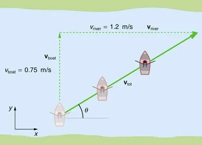
Figure 3.43 A boat attempts to travel straight across a river at a speed 0.75 m/s. The current in the river, however, flows at a speed of 1.20 m/s to the right. Image from OpenStax College Physics 2e, CC-BY 4.0
Image Description
The image is a diagram illustrating the motion of a boat crossing a river. It demonstrates the concept of vector addition and the impact of different velocities involved in the scenario.
The diagram shows a blue river with a represented flow from left to right. There are three positions of a boat depicted moving across the river.
- The boat’s own velocity (vboat) is 0.75 meters per second, represented by a solid black arrow pointing upward, perpendicular to the river’s flow.
- The river’s current velocity (vriver) is 1.2 meters per second, represented by a dashed green arrow pointing right along the flow of the river.
- The total velocity of the boat (vtot) is shown as a diagonal arrow in solid green, demonstrating the result of combining the boat and river velocities.
The diagram also includes an angle (θ) between the boat’s velocity and the resulting vector, indicating the deviation due to the river’s influence.
In the bottom left corner, an x-y coordinate system is displayed with y pointing upward and x pointing to the right.
Refer to Figure 3.43, which shows a boat trying to go straight across the river. Let us calculate the magnitude and direction of the boat’s velocity relative to an observer on the shore, [latex]\textbf{v}_{\text{tot}}[/latex]. The velocity of the boat, [latex]\textbf{v}_{\text{boat}}[/latex], is 0.75 m/s in the [latex]y[/latex]-direction relative to the river and the velocity of the river, [latex]\textbf{v}_{\text{river}}[/latex], is 1.20 m/s to the right.
Strategy
We start by choosing a coordinate system with its [latex]x[/latex]-axis parallel to the velocity of the river, as shown in Figure 3.43. Because the boat is directed straight toward the other shore, its velocity relative to the water is parallel to the [latex]y[/latex]-axis and perpendicular to the velocity of the river. Thus, we can add the two velocities by using the equations [latex]v_{\text{tot}} = \sqrt{v_{x}^{2} + v_{y}^{2}}[/latex] and [latex]\theta = \text{tan}^{- 1} \left(\right. v_{y} / v_{x} \left.\right)[/latex] directly.
Solution
The magnitude of the total velocity is
[latex]v_{\text{tot}} = \sqrt{v_{x}^{2} + v_{y}^{2}} ,[/latex]
where
[latex]v_{x} = v_{\text{river}} = 1 . \text{20 m}/\text{s}[/latex]
and
[latex]v_{y} = v_{\text{boat}} = 0 . \text{750 m}/\text{s}.[/latex]
Thus,
[latex]v_{\text{tot}} = \sqrt{\left(\right. 1 . \text{20 m}/\text{s} \left.\right)^{2} + \left(\right. 0 . \text{750 m}/\text{s} \left.\right)^{2}}[/latex]
yielding
[latex]v_{\text{tot}} = 1 . \text{42 m}/\text{s}.[/latex]
The direction of the total velocity [latex]\theta[/latex] is given by:
[latex]\theta = \text{tan}^{- 1} \left(\right. v_{y} / v_{x} \left.\right) = \text{tan}^{- 1} \left(\right. 0 . \text{750} / 1 . \text{20} \left.\right) .[/latex]
This equation gives
[latex]\theta = \text{32} . 0º .[/latex]
Discussion
Both the magnitude [latex]v[/latex] and the direction [latex]\theta[/latex] of the total velocity are consistent with Figure 3.43. Note that because the velocity of the river is large compared with the velocity of the boat, it is swept rapidly downstream. This result is evidenced by the small angle (only [latex]32.0º[/latex]) the total velocity has relative to the riverbank.
Example 3.7
Calculating Velocity: Wind Velocity Causes an Airplane to Drift
Calculate the wind velocity for the situation shown in Figure 3.44. The plane is known to be moving at 45.0 m/s due north relative to the air mass, while its velocity relative to the ground (its total velocity) is 38.0 m/s in a direction [latex]\text{20} .\text{0}º[/latex] west of north.
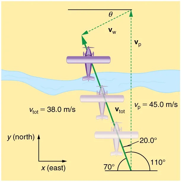
Figure 3.44 An airplane is known to be heading north at 45.0 m/s, though its velocity relative to the ground is 38.0 m/s at an angle west of north. What is the speed and direction of the wind? Image from OpenStax College Physics 2e, CC-BY 4.0
Image Description
The image depicts a diagram of an airplane flying over a river, used to illustrate vector addition. It shows the path of the airplane and associated velocity vectors. Here’s a description of the elements:
– A light purple airplane is shown flying in the sky, above a river that runs horizontally.
– Three vectors are illustrated:
– \( v_{\text{p}} \): Representing the plane’s velocity vector (45.0 m/s). It is vertical in the diagram.
– \( v_{\text{w}} \): Representing the wind’s velocity vector, shown at an angle \(\theta\).
– \( v_{\text{tot}} \): The total velocity vector (38.0 m/s), depicted at an oblique angle.
– The vectors form a triangle, where the sum of the plane’s velocity and wind’s velocity results in the total velocity.
– An angle of 20° is marked between the plane’s velocity vector and the total velocity vector.
– A coordinate system is shown in the bottom left corner, indicating north (y-axis) and east (x-axis).
– Several angles are annotated:
– 70°, representing the angle between the x-axis (east) and the total velocity vector.
– 110°, being the supplementary angle between the x-axis and the wind vector.
The image visually represents the relationship between the airplane’s velocity, the wind’s effect, and the resulting path of the airplane using vector addition principles.
Strategy
In this problem, somewhat different from the previous example, we know the total velocity [latex]\textbf{v}_{\text{tot}}[/latex] and that it is the sum of two other velocities, [latex]\textbf{v}_{\text{w}}[/latex] (the wind) and [latex]\textbf{v}_{\text{p}}[/latex] (the plane relative to the air mass). The quantity [latex]\textbf{v}_{\text{p}}[/latex] is known, and we are asked to find [latex]\textbf{v}_{\text{w}}[/latex]. None of the velocities are perpendicular, but it is possible to find their components along a common set of perpendicular axes. If we can find the components of [latex]\textbf{v}_{\text{w}}[/latex], then we can combine them to solve for its magnitude and direction. As shown in Figure 3.44, we choose a coordinate system with its x-axis due east and its y-axis due north (parallel to [latex]\textbf{v}_{\text{p}}[/latex]). (You may wish to look back at the discussion of the addition of vectors using perpendicular components in 3.3 Vector Addition and Subtraction: Analytical Methods.)
Solution
Because [latex]\textbf{v}_{\text{tot}}[/latex] is the vector sum of the [latex]\textbf{v}_{\text{w}}[/latex] and [latex]\textbf{v}_{\text{p}}[/latex], its x– and y-components are the sums of the x– and y-components of the wind and plane velocities. Note that the plane only has vertical component of velocity so [latex]v_{p x} = 0[/latex] and [latex]v_{p y} = v_{\text{p}}[/latex]. That is,
[latex]v_{\text{tot} x} = v_{\text{w} x}[/latex]
and
[latex]v_{\text{tot} y} = v_{\text{w} y} + v_{\text{p}} .[/latex]
We can use the first of these two equations to find [latex]v_{\text{w} x}[/latex]:
[latex]v_{\text{w} x} = v_{\text{tot} x} = v_{\text{tot}} \text{cos 110}º .[/latex]
Because [latex]v_{\text{tot}} = \text{38} . 0 m / \text{s}[/latex] and [latex]\text{cos 110}º = – 0.342[/latex] we have
[latex]v_{\text{w} x} = \left(\right. \text{38}.\text{0 m}/\text{s} \left.\right) \left(\right. –\text{0}.\text{342} \left.\right) = –\text{13 m}/\text{s}.[/latex]
The minus sign indicates motion west which is consistent with the diagram.
Now, to find [latex]v_{\text{w} \text{y}}[/latex] we note that
[latex]v_{\text{tot} y} = v_{\text{w} y} + v_{\text{p}}[/latex]
Here [latex]v_{\text{tot} y} = v_{\text{tot}} \text{sin}\textrm{ }\text{110}º[/latex]; thus,
[latex]\begin{align*}v_{\text{w} y} &= \left(\right. \text{38} . 0 m/s \left.\right) \left(\right. 0 . \text{940} \left.\right) - \text{45} . 0 m/s\\ &= - 9 . \text{29 m}/\text{s}.\end{align*}[/latex]
This minus sign indicates motion south which is consistent with the diagram.
Now that the perpendicular components of the wind velocity [latex]v_{\text{w} x}[/latex] and [latex]v_{\text{w} y}[/latex] are known, we can find the magnitude and direction of [latex]\textbf{v}_{\text{w}}[/latex]. First, the magnitude is
[latex]\begin{eqnarray*}v_{\text{w}} & = & \sqrt{v_{\text{w} x}^{2} + v_{\text{w} y}^{2}} \\ & = & \sqrt{\left(\right. - \text{13} . 0 m/s \left.\right)^{2} + \left(\right. - 9 . \text{29 m}/\text{s} \left.\right)^{2}}\end{eqnarray*}[/latex]
so that
[latex]v_{\text{w}} = \text{16} . 0 m/s .[/latex]
The direction is:
[latex]\theta = \text{tan}^{- 1} \left(\right. v_{\text{w} y} / v_{\text{w} x} \left.\right) = \text{tan}^{- 1} \left(\right. - 9 . \text{29} / - \text{13} . 0 \left.\right)[/latex]
giving
[latex]\theta = \text{35} . 6º .[/latex]
Discussion
The wind’s speed and direction are consistent with the significant effect the wind has on the total velocity of the plane, as seen in Figure 3.44. Because the plane is fighting a strong combination of crosswind and head-wind, it ends up with a total velocity significantly less than its velocity relative to the air mass as well as heading in a different direction.
Note that in both of the last two examples, we were able to make the mathematics easier by choosing a coordinate system with one axis parallel to one of the velocities. We will repeatedly find that choosing an appropriate coordinate system makes problem solving easier. For example, in projectile motion we always use a coordinate system with one axis parallel to gravity.
Relative Velocities and Classical Relativity
When adding velocities, we have been careful to specify that the velocity is relative to some reference frame. These velocities are called relative velocities. For example, the velocity of an airplane relative to an air mass is different from its velocity relative to the ground. Both are quite different from the velocity of an airplane relative to its passengers (which should be close to zero). Relative velocities are one aspect of relativity, which is defined to be the study of how different observers moving relative to each other measure the same phenomenon.
Nearly everyone has heard of relativity and immediately associates it with Albert Einstein (1879–1955), the greatest physicist of the 20th century. Einstein revolutionized our view of nature with his modern theory of relativity, which we shall study in later chapters. The relative velocities in this section are actually aspects of classical relativity, first discussed correctly by Galileo and Isaac Newton. Classical relativity is limited to situations where speeds are less than about 1% of the speed of light—that is, less than [latex]\text{3},\text{000}\textrm{ }\text{km}/\text{s}[/latex]. Most things we encounter in daily life move slower than this speed.
Let us consider an example of what two different observers see in a situation analyzed long ago by Galileo. Suppose a sailor at the top of a mast on a moving ship drops their binoculars. Where will it hit the deck? Will it hit at the base of the mast, or will it hit behind the mast because the ship is moving forward? The answer is that if air resistance is negligible, the binoculars will hit at the base of the mast at a point directly below its point of release. Now let us consider what two different observers see when the binoculars drop. One observer is on the ship and the other on shore. The binoculars have no horizontal velocity relative to the observer on the ship, and so he sees them fall straight down the mast. (See Figure 3.45.) To the observer on shore, the binoculars and the ship have the same horizontal velocity, so both move the same distance forward while the binoculars are falling. This observer sees the curved path shown in Figure 3.45. Although the paths look different to the different observers, each sees the same result—the binoculars hit at the base of the mast and not behind it. To get the correct description, it is crucial to correctly specify the velocities relative to the observer.
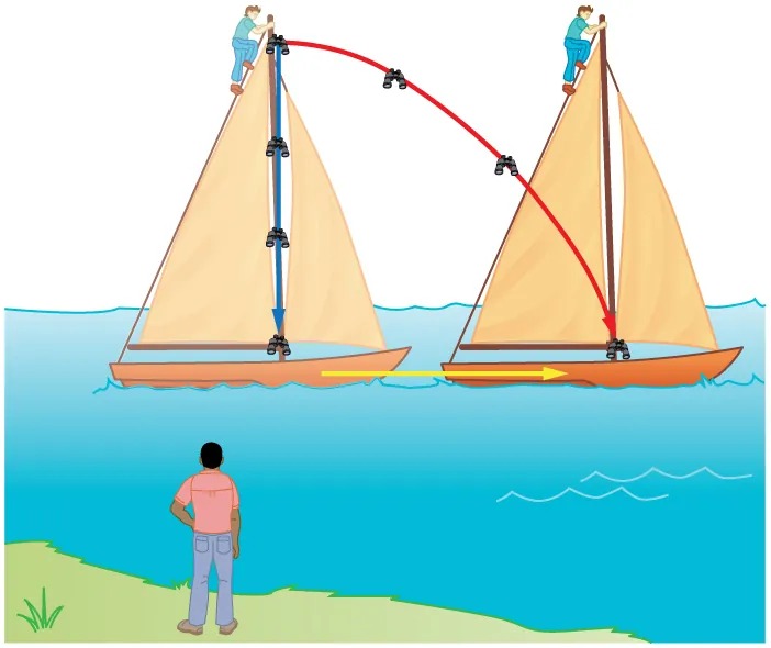
Figure 3.45 Classical relativity. The same motion as viewed by two different observers. An observer on the moving ship sees the binoculars dropped from the top of its mast fall straight down. An observer on shore sees the binoculars take the curved path, moving forward with the ship. Both observers see the binoculars strike the deck at the base of the mast. The initial horizontal velocity is different relative to the two observers. Image from OpenStax College Physics 2e, CC-BY 4.0
Image Description
The image illustrates two sailboats on a body of water. Both sailboats have tan sails and brown hulls.
– Left Sailboat:
– A person is perched at the top of the mast.
– A blue arrow runs vertically down the mast to indicate downward movement.
– A yellow arrow underneath the boat indicates its forward movement toward the right.
– Right Sailboat:
– Another person is at the top of its mast.
– A red curving arrow points from the top of the mast of the left sailboat to the mast of the right sailboat, suggesting a transfer or movement between the masts.
– A yellow arrow indicates the rightward movement under this boat as well.
A person stands on the grassy shore in the foreground, observing the scene. The sky is clear, and there are small wave patterns on the water.
Example 3.8
Calculating Relative Velocity: An Airline Passenger Drops a Coin
An airline passenger drops a coin while the plane is moving at 260 m/s. What is the velocity of the coin when it strikes the floor 1.50 m below its point of release: (a) Measured relative to the plane? (b) Measured relative to the Earth?
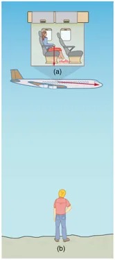
Figure 3.46 The motion of a coin dropped inside an airplane as viewed by two different observers. (a) An observer in the plane sees the coin fall straight down. (b) An observer on the ground sees the coin move almost horizontally. Image from OpenStax College Physics 2e, CC-BY 4.0
Image Description
The image consists of two parts, labeled (a) and (b).
– Part (a): This section shows the interior of an airplane cabin. Inside, there are two passenger seats. A person is seated on the left, with a red arrow pointing straight down from his position, indicating the path of a coin falling from the point of view of an observer in the airplane’s cabin.
– Part (b): This section shows an exterior side view of an airplane flying in the sky. Below the airplane stands a person on the ground looking up at it. The individual is shown from the back, wearing a red shirt and blue pants, against a clear sky background. A red arrow pointing to the right (the direction the plane is flying) and angle slightly down indicates the coin’s path as observed from the ground.
Together, these sections illustrate a concept combining aspects of passenger awareness inside an aircraft and observation from the ground.
Strategy
Both problems can be solved with the techniques for falling objects and projectiles. In part (a), the initial velocity of the coin is zero relative to the plane, so the motion is that of a falling object (one-dimensional). In part (b), the initial velocity is 260 m/s horizontal relative to the Earth and gravity is vertical, so this motion is a projectile motion. In both parts, it is best to use a coordinate system with vertical and horizontal axes.
Solution for (a)
Using the given information, we note that the initial velocity and position are zero, and the final position is 1.50 m. The final velocity can be found using the equation:
[latex]v_{y}^{2} = v_{0 , y}^{2} - 2 g \left(\right. y - y_{0} \left.\right) .[/latex]
Substituting known values into the equation, we get
[latex]\begin{align*}v_{y}^{2} &= 0^{2} - 2 \left(\right. 9 . \text{80} \text{ m}/\text{s}^{2} \left.\right) \left(\right. - 1 . \text{50} \text{m} - 0 m \left.\right)\\ &= \text{29} . 4 \text{m}^{2} /\text{s}^{2}\end{align*}[/latex]
yielding
[latex]v_{y} = - 5 . \text{42 m}/\text{s}.[/latex]
We know that the square root of 29.4 has two roots: 5.42 and -5.42. We choose the negative root because we know that the velocity is directed downwards, and we have defined the positive direction to be upwards. There is no initial horizontal velocity relative to the plane and no horizontal acceleration, and so the motion is straight down relative to the plane.
Solution for (b)
Because the initial vertical velocity is zero relative to the ground and vertical motion is independent of horizontal motion, the final vertical velocity for the coin relative to the ground is [latex]v_{y} = - 5.42 \text{m}/\text{s}[/latex], the same as found in part (a). In contrast to part (a), there now is a horizontal component of the velocity. However, since there is no horizontal acceleration, the initial and final horizontal velocities are the same and
[latex]v_{x} = \text{260}\textrm{ }\text{m}/\text{s}[/latex]. The x– and y-components of velocity can be combined to find the magnitude of the final velocity:
[latex]v = \sqrt{v_{x}^{2} + v_{y}^{2}} .[/latex]
Thus,
[latex]v = \sqrt{\left(\right. \text{260 m}/\text{s} \left.\right)^{2} + \left(\right. - 5 . \text{42 m}/\text{s} \left.\right)^{2}}[/latex]
yielding
[latex]v = \text{260} . \text{06 m}/\text{s}.[/latex]
The direction is given by:
[latex]\theta = \text{tan}^{- 1} \left(\right. v_{y} / v_{x} \left.\right) = \text{tan}^{- 1} \left(\right. - 5 . \text{42} / \text{260} \left.\right)[/latex]
so that
[latex]\theta = \text{tan}^{- 1} \left(\right. - 0 . \text{0208} \left.\right) = - 1 . \text{19}º .[/latex]
Discussion
In part (a), the final velocity relative to the plane is the same as it would be if the coin were dropped from rest on the Earth and fell 1.50 m. This result fits our experience; objects in a plane fall the same way when the plane is flying horizontally as when it is at rest on the ground. This result is also true in moving cars. In part (b), an observer on the ground sees a much different motion for the coin. The plane is moving so fast horizontally to begin with that its final velocity is barely greater than the initial velocity. Once again, we see that in two dimensions, vectors do not add like ordinary numbers—the final velocity v in part (b) is not [latex]\left(\right. \text{260 }–\text{ 5} . \text{42} \left.\right) \textrm{ }\text{m}/\text{s}[/latex]; rather, it is [latex]\text{260} . \text{06}\textrm{ }\text{m}/\text{s}[/latex]. The velocity’s magnitude had to be calculated to five digits to see any difference from that of the airplane. The motions as seen by different observers (one in the plane and one on the ground) in this example are analogous to those discussed for the binoculars dropped from the mast of a moving ship, except that the velocity of the plane is much larger, so that the two observers see very different paths. (See Figure 3.46.) In addition, both observers see the coin fall 1.50 m vertically, but the one on the ground also sees it move forward 144 m (this calculation is left for the reader). Thus, one observer sees a vertical path, the other a nearly horizontal path.
Making Connections: Relativity and Einstein
Because Einstein was able to clearly define how measurements are made (some involve light) and because the speed of light is the same for all observers, the outcomes are spectacularly unexpected. Time varies with observer, energy is stored as increased mass, and more surprises await.
PhET Explorations
Motion in 2D
Try the “Motion in 2D” simulation to Learn about position, velocity, and acceleration vectors. Move the ball with the mouse or let the simulation move the ball in four types of motion (2 types of linear, simple harmonic, circle).
