3.1 Kinematics in Two Dimensions: An Introduction
Learning Objectives
By the end of this section, you will be able to:
- Observe that motion in two dimensions consists of horizontal and vertical components.
- Understand the independence of horizontal and vertical vectors in two-dimensional motion.
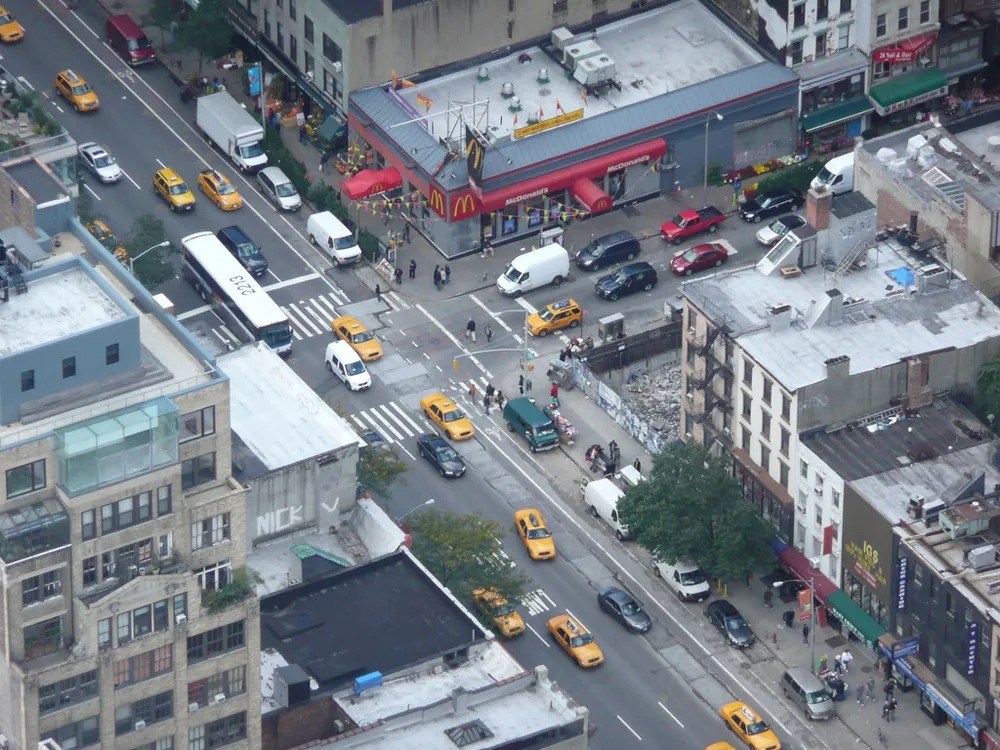
Figure 3.2 Walkers and drivers in a city like New York are rarely able to travel in straight lines to reach their destinations. Instead, they must follow roads and sidewalks, making two-dimensional, zigzagged paths. Image from OpenStax College Physics 2e, CC-BY 4.0
Two-Dimensional Motion: Walking in a City
Suppose you want to walk from one point to another in a city with uniform square blocks, as pictured in Figure 3.3.
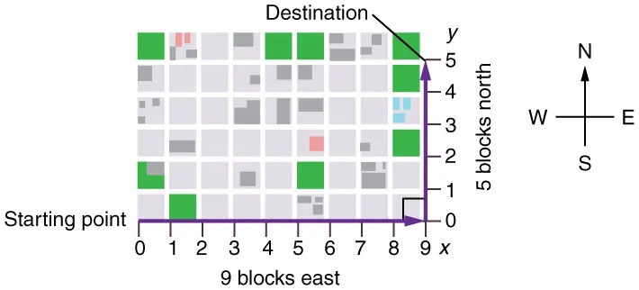
Figure 3.3 A pedestrian walks a two-dimensional path between two points in a city. In this scene, all blocks are square and are the same size. Image from OpenStax College Physics 2e, CC-BY 4.0
Image Description
The image depicts a grid map representing a route through a city with labeled axes and a compass rose for orientation.
| x-axis (9 blocks east) | ||||||||||
|---|---|---|---|---|---|---|---|---|---|---|
| y-axis | 0 | 1 | 2 | 3 | 4 | 5 | 6 | 7 | 8 | 9 |
| 5 blocks north | Destination | |||||||||
| 4 | ||||||||||
| 3 | ||||||||||
| 2 | ||||||||||
| 1 | ||||||||||
| 0 | Starting point | |||||||||
The grid is composed of several squares, some filled with colors. A thick purple line runs along the x-axis from 0 to 9 and up the y-axis from 0 to 5, marking a path from the “Starting point” at the lower right corner (0,0) to the “Destination” at the upper right corner (9,5), traveling east and then north. The map includes a compass indicating north, south, east, and west directions, positioned on the right side of the grid.
The straight-line path that a helicopter might fly is blocked to you as a pedestrian, and so you are forced to take a two-dimensional path, such as the one shown. You walk 14 blocks in all, 9 east followed by 5 north. What is the straight-line distance?
An old adage states that the shortest distance between two points is a straight line. The two legs of the trip and the straight-line path form a right triangle, and so the Pythagorean theorem, [latex]a^{2} \textrm{ }+\textrm{ } b^{2} \textrm{ }=\textrm{ } c^{2}[/latex], can be used to find the straight-line distance.
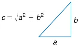
Figure 3.4 The Pythagorean theorem relates the length of the legs of a right triangle, labeled [latex]a[/latex] and [latex]b[/latex], with the hypotenuse, labeled [latex]c[/latex]. The relationship is given by: [latex]a^{2} +\textrm{ } b^{2} =\textrm{ } c^{2}[/latex]. This can be rewritten, solving for [latex]c[/latex] : [latex]c \textrm{ }=\textrm{ } \sqrt{a^{2} +\textrm{ } b^{2}}[/latex]. Image from OpenStax College Physics 2e, CC-BY 4.0
Image Description
The image shows a right-angled triangle next to a mathematical equation. The triangle is positioned with one angle at the bottom left and the right angle at the bottom right.
The sides are labeled as follows:
– The horizontal side at the bottom is labeled “a”.
– The vertical side on the right is labeled “b”.
– The hypotenuse, which is the slanted side, does not have a label on the triangle itself but is implied in the equation.
To the left of the triangle, there is the equation:
\[ c = \sqrt{a^2 + b^2} \]
This equation represents the Pythagorean theorem, describing the relationship between the lengths of the sides of a right-angled triangle. It states that the square of the hypotenuse \( c \) is equal to the sum of the squares of the other two sides \( a \) and \( b \).
The hypotenuse of the triangle is the straight-line path, and so in this case its length in units of city blocks is [latex]\sqrt{\left(\right. \text{9 blocks} \left.\right)^{2} +\textrm{ } \left(\right. \text{5 blocks} \left.\right)^{2}} =\textrm{ }\text{10} . \text{3 blocks}[/latex], considerably shorter than the 14 blocks you walked. (Note that we are using three significant figures in the answer. Although it appears that “9” and “5” have only one significant digit, they are discrete numbers. In this case “9 blocks” is the same as “9.0 or 9.00 blocks.” We have decided to use three significant figures in the answer in order to show the result more precisely.)
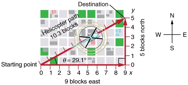
Figure 3.5 The straight-line path followed by a helicopter between the two points is shorter than the 14 blocks walked by the pedestrian. All blocks are square and the same size. Image from OpenStax College Physics 2e, CC-BY 4.0
Image Description
The image is a map diagram illustrating the path of a helicopter over a grid-like city layout. Here’s a detailed description:
– Grid Layout: The map shows a city grid with blocks marked by gray and white rectangles, intersected by streets. There are also green squares representing parks or open spaces scattered throughout the grid.
– Axes: The horizontal axis (x-axis) is labeled at the bottom, ranging from 0 to 9, representing blocks east. The vertical axis (y-axis) is on the right side, ranging from 0 to 5, representing blocks north.
– Path: A thick red arrow represents the helicopter’s path, starting at the bottom left labeled as “Starting point” and ending at the top right labeled as “Destination.” The path covers 9 blocks east and 5 blocks north.
– Measurements: The path has a diagonal distance labeled “Helicopter path 10.3 blocks.” The angle θ is marked at the starting point as 29.1° from the horizontal axis.
– Compass Rose: To the right of the grid, there is a compass rose indicating cardinal directions with “N” for north pointing upwards, “E” for east pointing to the right, “S” for south pointing downwards, and “W” for west pointing left.
This image visually demonstrates vector navigation on a grid, showing direction, distance, and angle.
The fact that the straight-line distance (10.3 blocks) in Figure 3.5 is less than the total distance walked (14 blocks) is one example of a general characteristic of vectors. (Recall that vectors are quantities that have both magnitude and direction.)
As for one-dimensional kinematics, we use arrows to represent vectors. The length of the arrow is proportional to the vector’s magnitude. The arrow’s length is indicated by hash marks in Figure 3.3 and Figure 3.5. The arrow points in the same direction as the vector. For two-dimensional motion, the path of an object can be represented with three vectors: one vector shows the straight-line path between the initial and final points of the motion, one vector shows the horizontal component of the motion, and one vector shows the vertical component of the motion. The horizontal and vertical components of the motion add together to give the straight-line path. For example, observe the three vectors in Figure 3.5. The first represents a 9-block displacement east. The second represents a 5-block displacement north. These vectors are added to give the third vector, with a 10.3-block total displacement. The third vector is the straight-line path between the two points. Note that in this example, the vectors that we are adding are perpendicular to each other and thus form a right triangle. This means that we can use the Pythagorean theorem to calculate the magnitude of the total displacement. (Note that we cannot use the Pythagorean theorem to add vectors that are not perpendicular. We will develop techniques for adding vectors having any direction, not just those perpendicular to one another, in Vector Addition and Subtraction: Graphical Methods and Vector Addition and Subtraction: Analytical Methods.)
The Independence of Perpendicular Motions
The person taking the path shown in Figure 3.5 walks east and then north (two perpendicular directions). How far they walk east is only affected by their motion eastward. Similarly, how far they walk north is only affected by their motion northward.
Independence of Motion
The horizontal and vertical components of two-dimensional motion are independent of each other. Any motion in the horizontal direction does not affect motion in the vertical direction, and vice versa.
This is true in a simple scenario like that of walking in one direction first, followed by another. It is also true of more complicated motion involving movement in two directions at once. For example, let’s compare the motions of two baseballs. One baseball is dropped from rest. At the same instant, another is thrown horizontally from the same height and follows a curved path. A stroboscope has captured the positions of the balls at fixed time intervals as they fall.
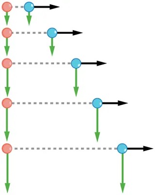
Figure 3.6 This shows the motions of two identical balls—one falls from rest, the other has an initial horizontal velocity. Each subsequent position is an equal time interval. Arrows represent horizontal and vertical velocities at each position. The ball on the right has an initial horizontal velocity, while the ball on the left has no horizontal velocity. Despite the difference in horizontal velocities, the vertical velocities and positions are identical for both balls. This shows that the vertical and horizontal motions are independent. Image from OpenStax College Physics 2e, CC-BY 4.0
Image Description
The image is a diagram representing a process flow with colored circles connected by arrows. Here’s a textual description:
– The diagram consists of two types of circles: red and blue.
– Each red circle is connected to a blue circle by a dashed horizontal line.
– From each blue circle, a black arrow points to the right.
– From each red circle, a green arrow points downwards.
– The sequence starts at the top with a red circle linked horizontally to a blue circle, followed by a right-pointing black arrow.
– The process repeats multiple times down the diagram, with each level following the same pattern:
– A red circle connected to a blue circle horizontally,
– A green arrow pointing down from each red circle,
– A black arrow pointing right from each blue circle.
The diagram visually represents a step-by-step flow from left to right, while progress continues downward from step to step.
It is remarkable that for each flash of the strobe, the vertical positions of the two balls are the same. This similarity implies that the vertical motion is independent of whether or not the ball is moving horizontally. (Assuming no air resistance, the vertical motion of a falling object is influenced by gravity only, and not by any horizontal forces.) Careful examination of the ball thrown horizontally shows that it travels the same horizontal distance between flashes. This is due to the fact that there are no additional forces on the ball in the horizontal direction after it is thrown. This result means that the horizontal velocity is constant, and affected neither by vertical motion nor by gravity (which is vertical). Note that this case is true only for ideal conditions. In the real world, air resistance will affect the speed of the balls in both directions.
The two-dimensional curved path of the horizontally thrown ball is composed of two independent one-dimensional motions (horizontal and vertical). The key to analyzing such motion, called projectile motion, is to resolve (break) it into motions along perpendicular directions. Resolving two-dimensional motion into perpendicular components is possible because the components are independent. We shall see how to resolve vectors in Vector Addition and Subtraction: Graphical Methods and Vector Addition and Subtraction: Analytical Methods. We will find such techniques to be useful in many areas of physics.
PhET Explorations
Ladybug Motion 2D
Learn about position, velocity and acceleration vectors. Move the ladybug by setting the position, velocity or acceleration, and see how the vectors change. Choose linear, circular or elliptical motion, and record and playback the motion to analyze the behavior.
