17.7 Magnetic Force on a Current-Carrying Conductor
Learning Objectives
By the end of this section, you will be able to:
- Describe the effects of a magnetic force on a current-carrying conductor.
- Calculate the magnetic force on a current-carrying conductor.
Because charges ordinarily cannot escape a conductor, the magnetic force on charges moving in a conductor is transmitted to the conductor itself.
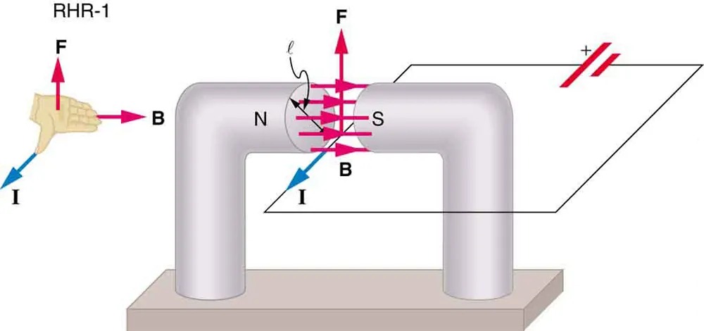
Figure 17.29 The magnetic field exerts a force on a current-carrying wire in a direction given by the right hand rule 1 (the same direction as that on the individual moving charges). This force can easily be large enough to move the wire, since typical currents consist of very large numbers of moving charges. Image from OpenStax College Physics 2e, CC-BY 4.0
Image Description
The image depicts a metallic pipe bent into a U-shape with ends anchored on a base. The pipe represents a conductor in a magnetic field. Key elements include:
- RHR-1: Shown as an upward-facing left hand demonstrating the right-hand rule (RHR-1).
- Arrows: Various colored arrows represent different physical quantities.
- I: Blue arrow pointing along the wire, indicating the direction of current flow.
- F: Red arrows showing the direction of magnetic force acting on the wire.
- B: Pink arrows pointing horizontally, indicating the direction of the magnetic field.
- N and S: Labels for the north (N) and south (S) poles on either side of the curved section of the pipe, indicating the orientation of the magnetic field.
- Battery Symbol: A symbol representing a battery is shown connected to the circuit, with positive and negative terminals marked.
The image serves as an illustration in electromagnetism to demonstrate how current, magnetic field, and force relate through the right-hand rule.
We can derive an expression for the magnetic force on a current by taking a sum of the magnetic forces on individual charges. (The forces add because they are in the same direction.) The force on an individual charge moving at the drift velocity [latex]v_{d}[/latex] is given by [latex]F = \text{qv}_{d} B \text{sin} \theta[/latex]. Taking [latex]B[/latex] to be uniform over a length of wire [latex]l[/latex] and zero elsewhere, the total magnetic force on the wire is then [latex]F = \left(\right. \text{qv}_{d} B \text{sin} \theta \left.\right) \left(\right. N \left.\right)[/latex], where [latex]N[/latex] is the number of charge carriers in the section of wire of length [latex]l[/latex]. Now, [latex]N = \text{nV}[/latex], where [latex]n[/latex] is the number of charge carriers per unit volume and [latex]V[/latex] is the volume of wire in the field. Noting that [latex]V = \text{Al}[/latex], where [latex]A[/latex] is the cross-sectional area of the wire, then the force on the wire is [latex]F = \left(\right. \text{qv}_{d} B \text{sin} \theta \left.\right) \left(\right. \text{nAl} \left.\right)[/latex]. Gathering terms,
[latex]F = \left(\right. \text{nqAv}_{d} \left.\right) \text{lB} \text{sin} \theta .[/latex]
Because [latex]\text{nqAv}_{d} = I[/latex] (see Current),
[latex]F = \text{IlB} \text{sin} \theta[/latex]
is the equation for magnetic force on a length [latex]l[/latex] of wire carrying a current [latex]I[/latex] in a uniform magnetic field [latex]B[/latex], as shown in Figure 17.30. If we divide both sides of this expression by [latex]l[/latex], we find that the magnetic force per unit length of wire in a uniform field is [latex]\frac{F}{l} = \text{IB} \text{sin} \theta[/latex]. The direction of this force is given by RHR-1, with the thumb in the direction of the current [latex]I[/latex]. Then, with the fingers in the direction of [latex]B[/latex], a perpendicular to the palm points in the direction of [latex]F[/latex], as in Figure 17.30.
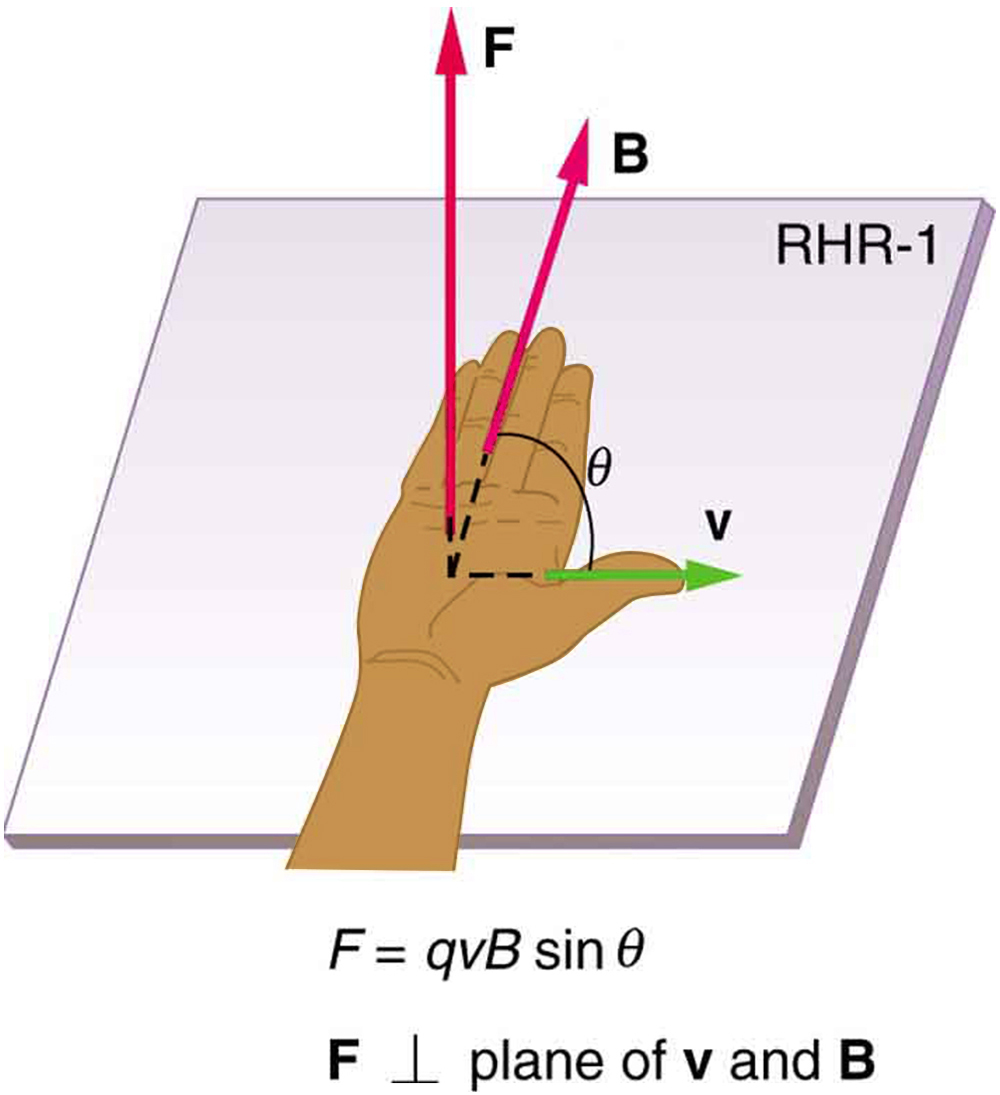
Image Description
The image illustrates the Right-Hand Rule Number 1 (RHR-1), commonly used in physics to determine the direction of the force acting on a charged particle moving through a magnetic field. In the image, a hand is positioned with the thumb, index, and middle fingers perpendicular to each other.
- Thumb (labeled “v”): This represents the direction of the velocity of the charged particle, pointing to the right.
- Index finger (labeled “B”): This indicates the direction of the magnetic field, pointing upwards and slightly towards the observer.
- Middle finger (labeled “F”): This shows the direction of the magnetic force exerted on the charged particle, pointing directly upward, forming a 90-degree angle with the plane created by “v” and “B”.
There is a mathematical expression shown below the hand: F = qvB sin θ, which describes the magnitude of the force, where q is the charge, v is the velocity, B is the magnetic field strength, and θ is the angle between v and B. The text also mentions that F is perpendicular to the plane formed by v and B.
Example 17.4
Calculating Magnetic Force on a Current-Carrying Wire: A Strong Magnetic Field
Calculate the force on the wire shown in Figure 17.29, given [latex]B = 1 . \text{50 T}[/latex], [latex]l = 5 . \text{00 cm}[/latex], and [latex]I = \text{20} . 0 \text{A}[/latex].
Strategy
The force can be found with the given information by using [latex]F = \text{IlB} \text{sin} \theta[/latex] and noting that the angle [latex]\theta[/latex] between [latex]I[/latex] and [latex]B[/latex] is [latex]\text{90}º[/latex], so that [latex]\text{sin} \theta = 1[/latex].
Solution
Entering the given values into [latex]F = \text{IlB} \text{sin} \theta[/latex] yields
[latex]\begin{align*}F &= \text{IlB} \text{sin} \theta\\ &= \left(\text{20} .\text{0 A}\right) \left(0 . \text{0500 m}\right) \left(1 . \text{50 T}\right) \left(1\right) \text{ }.\end{align*}[/latex]
The units for tesla are [latex]\text{1 T} = \frac{N}{A \cdot m}[/latex]; thus,
[latex]F = 1 . \text{50 N}.[/latex]
Discussion
This large magnetic field creates a significant force on a small length of wire.
Magnetic force on current-carrying conductors is used to convert electric energy to work. (Motors are a prime example—they employ loops of wire and are considered in the next section.) Magnetohydrodynamics (MHD) is the technical name given to a clever application where magnetic force pumps fluids without moving mechanical parts. (See Figure 17.31.)
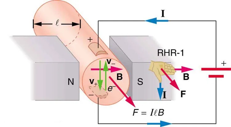
Figure 17.31 Magnetohydrodynamics. The magnetic force on the current passed through this fluid can be used as a nonmechanical pump. Image from OpenStax College Physics 2e, CC-BY 4.0
Image Description
The image depicts a diagram illustrating the interaction between a magnetic field and an electric current. It shows a cylindrical conductor placed between the north (N) and south (S) poles of a magnet. The magnetic field lines (B) are represented by pink arrows pointing from N to S. An electric current (I) is flowing through the conductor, represented by blue arrows.
The force (F) acting on the conductor is shown with a red arrow, perpendicular to both the magnetic field and the current. The force direction is determined using the right-hand rule (RHR-1), depicted by a right hand with fingers pointing in the direction of the current and the thumb pointing in the direction of the force.
There are additional green arrows inside the conductor, labeled as velocity (V) and electron movement (e-). The notation \( F = I\ell B \) indicates the formula for calculating the magnetic force on the conductor, where \( I \) is the current, \( \ell \) is the length of the conductor within the magnetic field, and \( B \) is the magnetic field strength.
A strong magnetic field is applied across a tube and a current is passed through the fluid at right angles to the field, resulting in a force on the fluid parallel to the tube axis as shown. The absence of moving parts makes this attractive for moving a hot, chemically active substance, such as the liquid sodium employed in some nuclear reactors. Experimental artificial hearts are testing with this technique for pumping blood, perhaps circumventing the adverse effects of mechanical pumps. (Cell membranes, however, are affected by the large fields needed in MHD, delaying its practical application in humans.) MHD propulsion for nuclear submarines has been proposed, because it could be considerably quieter than conventional propeller drives. The deterrent value of nuclear submarines is based on their ability to hide and survive a first or second nuclear strike. As we slowly disassemble our nuclear weapons arsenals, the submarine branch will be the last to be decommissioned because of this ability (See Figure 22.32.) Existing MHD drives are heavy and inefficient—much development work is needed.
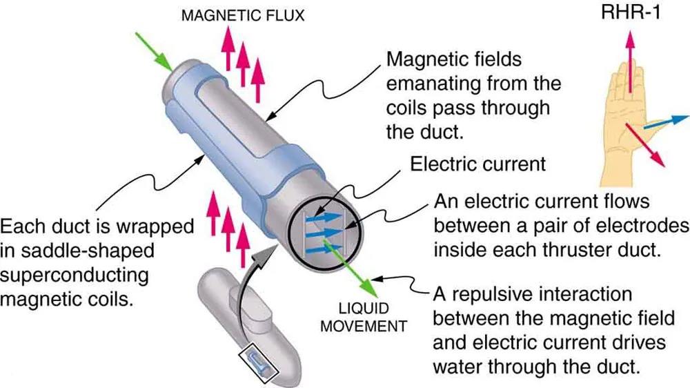
Figure 17.32 An MHD propulsion system in a nuclear submarine could produce significantly less turbulence than propellers and allow it to run more silently. The development of a silent drive submarine was dramatized in the book and the film The Hunt for Red October. Image from OpenStax College Physics 2e, CC-BY 4.0
Image Description
The image depicts a schematic diagram of a propulsion system featuring saddle-shaped superconducting magnetic coils wrapped around a duct. The process includes the following key components and interactions:
- Magnetic coils: Each duct is wrapped in these superconducting coils, which generate magnetic fields.
- Magnetic flux: The magnetic fields, represented by pink arrows, emanate from the coils and pass through the duct.
- Electric current: An electric current flows between a pair of electrodes inside each thruster duct, indicated by blue arrows.
- Liquid movement: The interaction of the magnetic field and electric current creates a repulsive force that drives water through the duct, represented by a green arrow.
Additionally, a reference hand labeled “RHR-1” (Right-Hand Rule 1) illustrates the direction of the magnetic field, electric current, and force vector. The thumb points upwards, the index finger to the right, and the middle finger outwards, demonstrating the mutually perpendicular relationship of these vectors.
