17.3 Magnetic Fields and Magnetic Field Lines
Learning Objectives
By the end of this section, you will be able to:
- Define magnetic field and describe the magnetic field lines of various magnetic fields.
Einstein is said to have been fascinated by a compass as a child, perhaps musing on how the needle felt a force without direct physical contact. His ability to think deeply and clearly about action at a distance, particularly for gravitational, electric, and magnetic forces, later enabled him to create his revolutionary theory of relativity. Since magnetic forces act at a distance, we define a magnetic field to represent magnetic forces. The pictorial representation of magnetic field lines is very useful in visualizing the strength and direction of the magnetic field. As shown in Figure 17.14, the direction of magnetic field lines is defined to be the direction in which the north end of a compass needle points. The magnetic field is traditionally called the B-field.
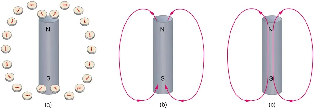
Figure 17.14 Magnetic field lines are defined to have the direction that a small compass points when placed at a location. (a) If small compasses are used to map the magnetic field around a bar magnet, they will point in the directions shown: away from the north pole of the magnet, toward the south pole of the magnet. (Recall that the Earth’s north magnetic pole is really a south pole in terms of definitions of poles on a bar magnet.) (b) Connecting the arrows gives continuous magnetic field lines. The strength of the field is proportional to the closeness (or density) of the lines. (c) If the interior of the magnet could be probed, the field lines would be found to form continuous closed loops. Image from OpenStax College Physics 2e, CC-BY 4.0
Image Description
The image consists of three illustrations labeled (a), (b), and (c), depicting magnetic fields around a cylindrical magnet:
(a) The first illustration shows a cylindrical magnet with a north (N) pole on top and a south (S) pole at the bottom. Surrounding the magnet are small circular symbols representing atoms, each containing an arrow indicating random magnetic orientation.
(b) The second illustration depicts the same cylindrical magnet with magnetic field lines represented as red arrows curving outward from the north pole and returning to the south pole.
(c) The third illustration shows the same magnet with magnetic field lines forming continuous loops, moving from the north to the south pole, indicating a more uniform magnetic field structure.
Small compasses used to test a magnetic field will not disturb it. (This is analogous to the way we tested electric fields with a small test charge. In both cases, the fields represent only the object creating them and not the probe testing them.) Figure 17.15 shows how the magnetic field appears for a current loop and a long straight wire, as could be explored with small compasses. A small compass placed in these fields will align itself parallel to the field line at its location, with its north pole pointing in the direction of B. Note the symbols used for field into and out of the paper.
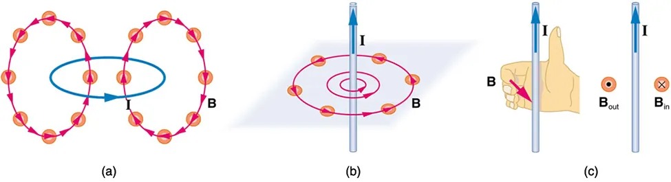
Figure 17.15 Small compasses could be used to map the fields shown here. (a) The magnetic field of a circular current loop is similar to that of a bar magnet. (b) A long and straight wire creates a field with magnetic field lines forming circular loops. (c) When the wire is in the plane of the paper, the field is perpendicular to the paper. Note that the symbols used for the field pointing inward (like the tail of an arrow) and the field pointing outward Image from OpenStax College Physics 2e, CC-BY 4.0
Image Description
This image consists of three diagrams labeled (a), (b), and (c) demonstrating the magnetic fields around a conducting wire with current.
(a) The first diagram shows two loops of circular arrows with a wire running vertically through the center. The arrows indicate the direction of the magnetic field. A current labeled “I” flows upward through the wire. The magnetic field lines, labeled “B,” surround the wire in circular loops, suggesting the right-hand rule.
(b) The second diagram shows a single wire oriented vertically with circular magnetic field lines around it, also following the right-hand rule. The current “I” flows upward through the wire while the magnetic field lines “B” surround the wire in a circular pattern, perpendicular to the wire.
(c) The third diagram includes two sections. On the left, a vertical wire with current “I” flowing upward is shown alongside a right hand with the thumb pointing up, indicating the direction of the current. The curled fingers represent the direction of the magnetic field “B.” On the right, symbols “Bout” (a dot with a circle) and “Bin” (a cross with a circle) represent the magnetic field coming out and going into the page, respectively.
Making Connections: Concept of a Field
A field is a way of mapping forces surrounding any object that can act on another object at a distance without apparent physical connection. The field represents the object generating it. Gravitational fields map gravitational forces, electric fields map electrical forces, and magnetic fields map magnetic forces.
Extensive exploration of magnetic fields has revealed a number of hard-and-fast rules. We use magnetic field lines to represent the field (the lines are a pictorial tool, not a physical entity in and of themselves). The properties of magnetic field lines can be summarized by these rules:
- The direction of the magnetic field is tangent to the field line at any point in space. A small compass will point in the direction of the field line.
- The strength of the field is proportional to the closeness of the lines. It is exactly proportional to the number of lines per unit area perpendicular to the lines (called the areal density).
- Magnetic field lines can never cross, meaning that the field is unique at any point in space.
- Magnetic field lines are continuous, forming closed loops without beginning or end. They go from the north pole to the south pole.
The last property is related to the fact that the north and south poles cannot be separated. It is a distinct difference from electric field lines, which begin and end on the positive and negative charges. If magnetic monopoles existed, then magnetic field lines would begin and end on them.
