17.2 Ferromagnets and Electromagnets
Learning Objectives
By the end of this section, you will be able to:
- Define ferromagnet.
- Describe the role of magnetic domains in magnetization.
- Explain the significance of the Curie temperature.
- Describe the relationship between electricity and magnetism.
Ferromagnets
Only certain materials, such as iron, cobalt, nickel, and gadolinium, exhibit strong magnetic effects. Such materials are called ferromagnetic, after the Latin word for iron, ferrum. A group of materials made from the alloys of the rare earth elements are also used as strong and permanent magnets; a popular one is neodymium. Other materials exhibit weak magnetic effects, which are detectable only with sensitive instruments. Not only do ferromagnetic materials respond strongly to magnets (the way iron is attracted to magnets), they can also be magnetized themselves—that is, they can be induced to be magnetic or made into permanent magnets.
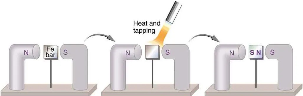
Figure 17.7 An unmagnetized piece of iron is placed between two magnets, heated, and then cooled, or simply tapped when cold. The iron becomes a permanent magnet with the poles aligned as shown: its south pole is adjacent to the north pole of the original magnet, and its north pole is adjacent to the south pole of the original magnet. Note that there are attractive forces between the magnets. Image from OpenStax College Physics 2e, CC-BY 4.0
Image Description
The image illustrates a three-step process involving magnets and a metal bar.
In the first panel, there is an iron (Fe) bar placed vertically on a base. It is situated between two large, bent magnets labeled ‘N’ for North and ‘S’ for South, respectively.
In the second panel, above the iron bar, there is a tool applying heat and tapping to the bar, indicating a process of heating and mechanical impact.
In the third panel, the central bar now displays magnetic poles labeled ‘N’ for North and ‘S’ for South, indicating that the iron bar has been magnetized. The bent magnets remain in the same positions.
When a magnet is brought near a previously unmagnetized ferromagnetic material, it causes local magnetization of the material with unlike poles closest, as in Figure 17.7. (This results in the attraction of the previously unmagnetized material to the magnet.) What happens on a microscopic scale is illustrated in Figure 17.8. The regions within the material called domains act like small bar magnets. Within domains, the poles of individual atoms are aligned. Each atom acts like a tiny bar magnet. Domains are small and randomly oriented in an unmagnetized ferromagnetic object. In response to an external magnetic field, the domains may grow to millimeter size, aligning themselves as shown in Figure 17.8(b). This induced magnetization can be made permanent if the material is heated and then cooled, or simply tapped in the presence of other magnets.
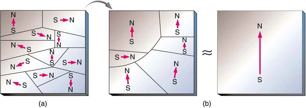
Figure 17.8 (a) An unmagnetized piece of iron (or other ferromagnetic material) has randomly oriented domains. (b) When magnetized by an external field, the domains show greater alignment, and some grow at the expense of others. Individual atoms are aligned within domains; each atom acts like a tiny bar magnet. Image from OpenStax College Physics 2e, CC-BY 4.0
Image Description
The image consists of three diagrams labeled (a), (b), and an unlabeled one depicting a transformation of magnetic domains:
(a) The left diagram shows a rectangular block divided into irregular sections, each with an arrow indicating the direction of magnetic poles. Some arrows point upwards with the letter ‘N’ (North) at the top and ‘S’ (South) at the bottom. Others point in various directions, showing that the magnetic domains are disordered.
(b) The middle diagram illustrates the same rectangular block with fewer divisions. The arrows now align uniformly upwards, with the letters ‘N’ at the top and ‘S’ at the bottom in each section, indicating partial alignment of magnetic domains.
The right diagram, connected to the middle one by a symbol indicating approximation or transformation, depicts a uniform block with one large arrow pointing upwards. It is labeled with ‘N’ at the top and ‘S’ at the bottom, signifying a fully aligned magnetic field throughout the block.
Conversely, a permanent magnet can be demagnetized by hard blows or by heating it in the absence of another magnet. Increased thermal motion at higher temperature can disrupt and randomize the orientation and the size of the domains. There is a well-defined temperature for ferromagnetic materials, which is called the Curie temperature, above which they cannot be magnetized. The Curie temperature for iron is 1043 K [latex]\left(\right. \text{770}º\text{C} \left.\right)[/latex], which is well above room temperature. There are several elements and alloys that have Curie temperatures much lower than room temperature and are ferromagnetic only below those temperatures.
Electromagnets
Early in the 19th century, it was discovered that electrical currents cause magnetic effects. The first significant observation was by the Danish scientist Hans Christian Oersted (1777–1851), who found that a compass needle was deflected by a current-carrying wire. This was the first significant evidence that the movement of charges had any connection with magnets. Electromagnetism is the use of electric current to make magnets. These temporarily induced magnets are called electromagnets. Electromagnets are employed for everything from a wrecking yard crane that lifts scrapped cars to controlling the beam of a 90-km-circumference particle accelerator to the magnets in medical imaging machines (See Figure 17.9).
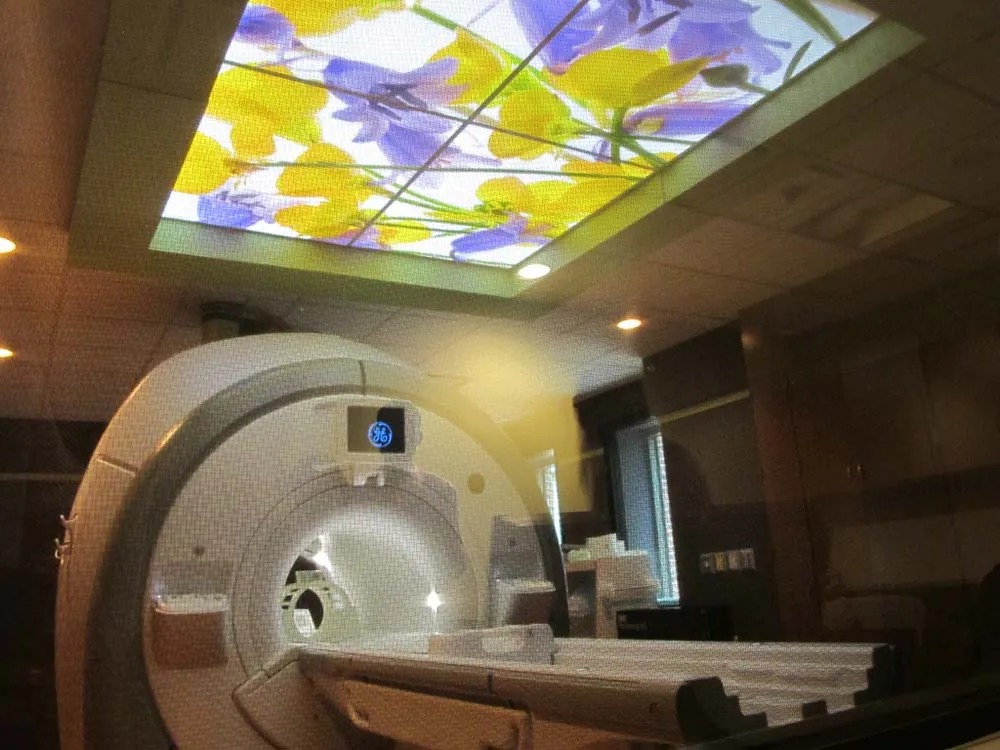
Figure 17.9 Instrument for magnetic resonance imaging (MRI). The device uses a superconducting cylindrical coil for the main magnetic field. The patient goes into this “tunnel” on the gurney. Image from OpenStax College Physics 2e, CC-BY 4.0
Figure 17.10 shows that the response of iron filings to a current-carrying coil and to a permanent bar magnet. The patterns are similar. In fact, electromagnets and ferromagnets have the same basic characteristics—for example, they have north and south poles that cannot be separated and for which like poles repel and unlike poles attract.
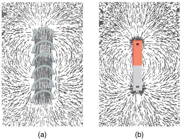
Figure 17.10 Iron filings near (a) a current-carrying coil and (b) a magnet act like tiny compass needles, showing the shape of their fields. Their response to a current-carrying coil and a permanent magnet is seen to be very similar, especially near the ends of the coil and the magnet. Image from OpenStax College Physics 2e, CC-BY 4.0
Image Description
The image is split into two sections, labeled (a) and (b), each depicting a different magnetic field representation.
(a) Magnetic Field Around a Solenoid: This section shows the magnetic field lines produced by a solenoid, which consists of a coil of wire. The solenoid is oriented vertically, and the field lines are densely concentrated inside the coil, indicating a strong magnetic field. Outside the solenoid, the field lines loop around, similar to the pattern of a bar magnet, forming closed curves.
(b) Magnetic Field Around a Bar Magnet: This section depicts the magnetic field lines of a bar magnet. The magnet is oriented vertically, with the north pole (N) at the top and the south pole (S) at the bottom. Field lines emerge from the north pole, loop around the magnet, and re-enter at the south pole, forming symmetrical, closed loops.
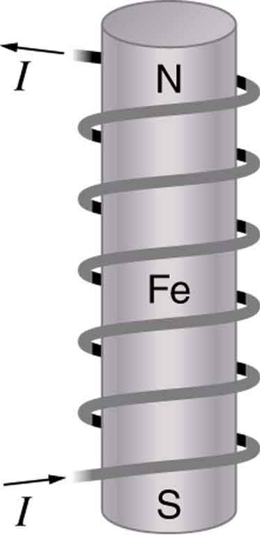
Combining a ferromagnet with an electromagnet can produce particularly strong magnetic effects. (See Figure 17.11.) Whenever strong magnetic effects are needed, such as lifting scrap metal, or in particle accelerators, electromagnets are enhanced by ferromagnetic materials. Limits to how strong the magnets can be made are imposed by coil resistance (it will overheat and melt at sufficiently high current), and so superconducting magnets may be employed. These are still limited, because superconducting properties are destroyed by too great a magnetic field.
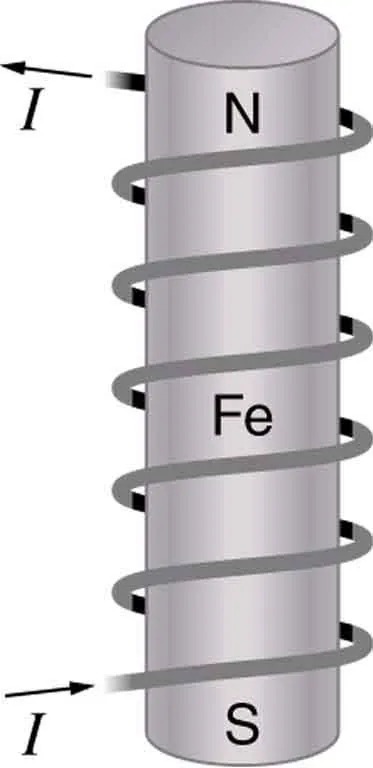
Image Description
The image depicts a diagram of an electromagnet. It shows a cylindrical iron core, labeled “Fe,” with a wire coil wrapped around it. The coil is shown as a helical path spiraling down the cylinder. The ends of the coil have arrows and are labeled “I,” indicating the direction of the electric current. The top and bottom ends of the cylinder are labeled “N” and “S,” representing the north and south poles of the electromagnet. This setup demonstrates how an electric current flowing through the coil creates a magnetic field, turning the iron core into a magnet.
Figure 17.12 shows a few uses of combinations of electromagnets and ferromagnets. Ferromagnetic materials can act as memory devices, because the orientation of the magnetic fields of small domains can be reversed or erased. Magnetic information storage on videotapes and computer hard drives are among the most common applications. This property is vital in our digital world.
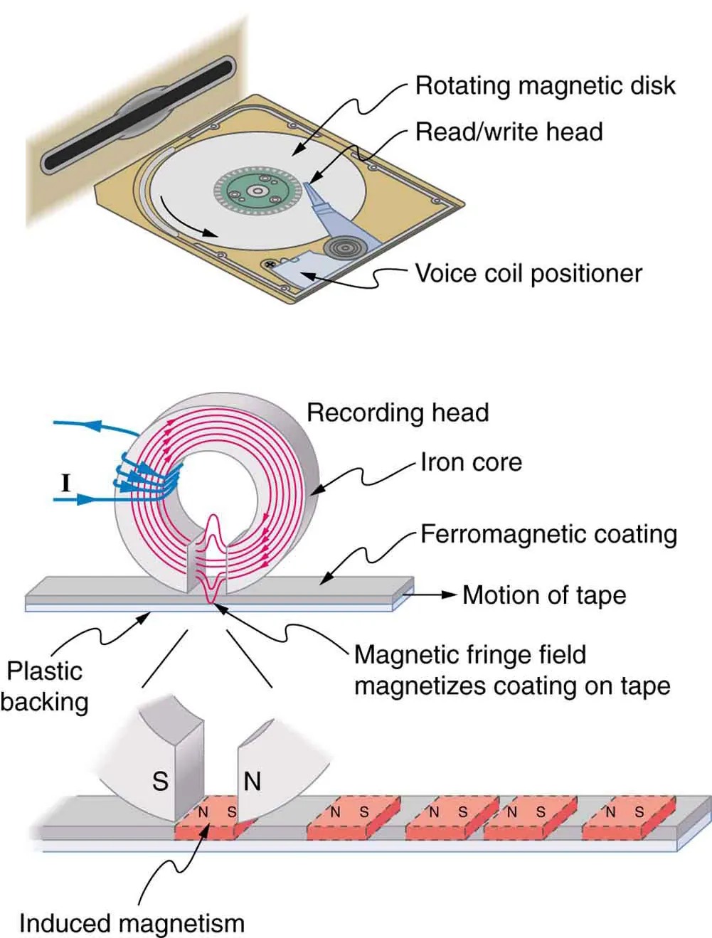
Figure 17.12 An electromagnet induces regions of permanent magnetism on a floppy disk coated with a ferromagnetic material. The information stored here is digital (a region is either magnetic or not); in other applications, it can be analog (with a varying strength), such as on audiotapes. Image from OpenStax College Physics 2e, CC-BY 4.0
Image Description
The image is a diagram showing the working principles of data storage using magnetic technology. It contains three main parts:
1. Top Section: A schematic of a hard disk drive. The components include:
- Rotating magnetic disk: A circular disc where data is stored magnetically.
- Read/write head: The tool that reads data from and writes data to the disk.
- Voice coil positioner: The mechanism that precisely moves the read/write head across the disk surface.
2. Middle Section: A diagram illustrating a recording head in a magnetic tape recorder. Components shown are:
- Recording head: This includes an iron core and coils where electric current flows, producing a magnetic field.
- Ferromagnetic coating: A coating on the tape that gets magnetized by the recording head.
- Motion of tape: Indicates the direction the tape moves under the recording head.
- Plastic backing: The base material of the tape providing support to the ferromagnetic coating.
- Magnetic fringe field: The magnetic field produced by the recording head that magnetizes the coating on the tape.
3. Bottom Section: A representation of how magnetism is induced in a magnetic medium, showing:
- Induced magnetism: The creation of magnetic poles (north ‘N’ and south ‘S’) in the tape due to the magnetic field.
Current: The Source of All Magnetism
An electromagnet creates magnetism with an electric current. In later sections we explore this more quantitatively, finding the strength and direction of magnetic fields created by various currents. But what about ferromagnets? Figure 17.13 shows models of how electric currents create magnetism at the submicroscopic level. (Note that we cannot directly observe the paths of individual electrons about atoms, and so a model or visual image, consistent with all direct observations, is made. We can directly observe the electron’s orbital angular momentum, its spin momentum, and subsequent magnetic moments, all of which are explained with electric-current-creating subatomic magnetism.) Currents, including those associated with other submicroscopic particles like protons, allow us to explain ferromagnetism and all other magnetic effects. Ferromagnetism, for example, results from an internal cooperative alignment of electron spins, possible in some materials but not in others.
Crucial to the statement that electric current is the source of all magnetism is the fact that it is impossible to separate north and south magnetic poles. (This is far different from the case of positive and negative charges, which are easily separated.) A current loop always produces a magnetic dipole—that is, a magnetic field that acts like a north pole and south pole pair. Since isolated north and south magnetic poles, called magnetic monopoles, are not observed, currents are used to explain all magnetic effects. If magnetic monopoles did exist, then we would have to modify this underlying connection that all magnetism is due to electrical current. There is no known reason that magnetic monopoles should not exist—they are simply never observed—and so searches at the subnuclear level continue. If they do not exist, we would like to find out why not. If they do exist, we would like to see evidence of them.
Electric Currents and Magnetism
Electric current is the source of all magnetism.
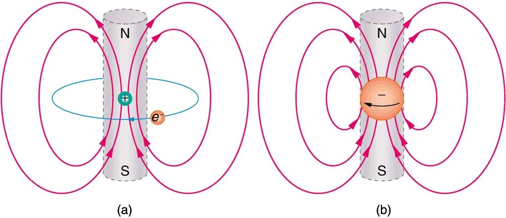
Figure 17.13 (a) In the planetary model of the atom, an electron orbits a nucleus, forming a closed-current loop and producing a magnetic field with a north pole and a south pole. (b) Electrons have spin and can be crudely pictured as rotating charge, forming a current that produces a magnetic field with a north pole and a south pole. Neither the planetary model nor the image of a spinning electron is completely consistent with modern physics. However, they do provide a useful way of understanding phenomena. Image from OpenStax College Physics 2e, CC-BY 4.0
Image Description
The image contains two diagrams labeled (a) and (b), illustrating magnetic fields.
Diagram (a):
- A cylindrical magnet is depicted with the top as the North (N) pole and the bottom as the South (S) pole.
- There are curved pink arrows, representing magnetic field lines, emerging from the North pole, looping around, and entering the South pole.
- A green circle with a positive sign (+) inside is located inside the loops, symbolizing a proton.
- A smaller orange circle with an “e” representing an electron is orbiting the proton in a circular blue path around the magnet.
Diagram (b):
-
- Similar to diagram (a), a cylindrical magnet is displayed with the North (N) pole on top and the South (S) pole at the bottom.
- The same curved pink arrows represent magnetic field lines, emerging from the North pole and entering the South pole.
- A large orange circle with a negative sign (−) inside is located in the center, representing a spinning electron.
- An arrow inside the orange circle indicates the direction of the electron’s spin.
PhET Explorations
Magnets and Electromagnets
Explore the interactions between a compass and bar magnet. Discover how you can use a battery and wire to make a magnet! Can you make it a stronger magnet? Can you make the magnetic field reverse?
