16.8 Resistors in Series and Parallel
Learning Objectives
By the end of this section, you will be able to:
- Draw a circuit with resistors in parallel and in series.
- Calculate the voltage drop of a current across a resistor using Ohm’s law.
- Contrast the way total resistance is calculated for resistors in series and in parallel.
- Explain why total resistance of a parallel circuit is less than the smallest resistance of any of the resistors in that circuit.
- Calculate total resistance of a circuit that contains a mixture of resistors connected in series and in parallel.
Most circuits have more than one component, called a resistor that limits the flow of charge in the circuit. A measure of this limit on charge flow is called resistance. The simplest combinations of resistors are the series and parallel connections illustrated in Figure 16.32. The total resistance of a combination of resistors depends on both their individual values and how they are connected.
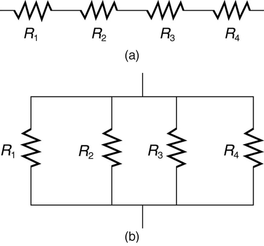
Figure 16.32 (a) A series connection of resistors. (b) A parallel connection of resistors. Image from OpenStax College Physics 2e, CC-BY 4.0
Image Description
The image shows two diagrams of electrical circuits with resistors.
(a) The top diagram depicts a series circuit with four resistors arranged in a line. They are labeled as R1, R2, R3, and R4, connected one after the other.
(b) The bottom diagram shows a parallel circuit with four resistors. They are labeled as R1, R2, R3, and R4, each connected separately between two common lines.
Resistors in Series
When are resistors in series? Resistors are in series whenever the flow of charge, called the current, must flow through devices sequentially. For example, if current flows through a person holding a screwdriver and into the Earth, then [latex]R_{1}[/latex] in Figure 16.32(a) could be the resistance of the screwdriver’s shaft, [latex]R_{2}[/latex] the resistance of its handle, [latex]R_{3}[/latex] the person’s body resistance, and [latex]R_{4}[/latex] the resistance of her shoes.
Figure 16.33 shows resistors in series connected to a voltage source. It seems reasonable that the total resistance is the sum of the individual resistances, considering that the current has to pass through each resistor in sequence. (This fact would be an advantage to a person wishing to avoid an electrical shock, who could reduce the current by wearing high-resistance rubber-soled shoes. It could be a disadvantage if one of the resistances were a faulty high-resistance cord to an appliance that would reduce the operating current.)
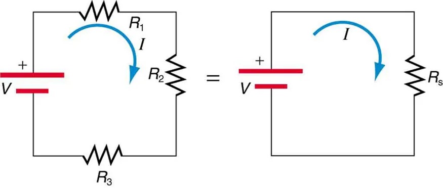
Figure 16.33 Three resistors connected in series to a battery (left) and the equivalent single or series resistance Image from OpenStax College Physics 2e, CC-BY 4.0
Image Description
The image contains two electrical circuits, shown side by side, with an equality sign between them. The left circuit consists of a voltage source labeled “V” indicated by red lines and a voltage symbol, connected in series with three resistors labeled “R1“, “R2“, and “R3“. An arrow with the label “I” indicates current direction flowing clockwise from the positive terminal through the resistors.
The right circuit shows a simplified version, with the same voltage source “V” and a single equivalent resistor labeled “Rs“. A similar arrow labeled “I” demonstrates the current flowing clockwise in this simplified circuit. This illustration represents the concept of reducing series resistors to a single equivalent resistor in an electrical circuit.
To verify that resistances in series do indeed add, let us consider the loss of electrical power, called a voltage drop, in each resistor in Figure 16.33.
According to Ohm’s law, the voltage drop, [latex]V[/latex], across a resistor when a current flows through it is calculated using the equation [latex]V = \text{IR}[/latex], where [latex]I[/latex] equals the current in amps (A) and [latex]R[/latex] is the resistance in ohms [latex]\left(\Omega\right)[/latex]. Another way to think of this is that [latex]V[/latex] is the voltage necessary to make a current [latex]I[/latex] flow through a resistance [latex]R[/latex].
So the voltage drop across [latex]R_{1}[/latex] is [latex]V_{1} = \mathit{IR}_{1}[/latex], that across [latex]R_{2}[/latex] is [latex]V_{2} = \mathit{IR}_{2}[/latex], and that across [latex]R_{3}[/latex] is [latex]V_{3} = \mathit{IR}_{3}[/latex]. The sum of these voltages equals the voltage output of the source; that is,
[latex]V = V_{1} + V_{2} + V_{3} .[/latex]
This equation is based on the conservation of energy and conservation of charge. Electrical potential energy can be described by the equation [latex]\text{PE} = \text{qV}[/latex], where [latex]q[/latex] is the electric charge and [latex]V[/latex] is the voltage. Thus the energy supplied by the source is [latex]\text{qV}[/latex], while that dissipated by the resistors is
[latex]\text{qV}_{1} + \text{qV}_{2} + \text{qV}_{3} .[/latex]
Connections: Conservation Laws
The derivations of the expressions for series and parallel resistance are based on the laws of conservation of energy and conservation of charge, which state that total charge and total energy are constant in any process. These two laws are directly involved in all electrical phenomena and will be invoked repeatedly to explain both specific effects and the general behavior of electricity.
These energies must be equal, because there is no other source and no other destination for energy in the circuit. Thus, [latex]\mathit{qV} = \mathit{qV}_{1} + \mathit{qV}_{2} + \mathit{qV}_{3}[/latex]. The charge [latex]q[/latex] cancels, yielding [latex]V = V_{1} + V_{2} + V_{3}[/latex], as stated. (Note that the same amount of charge passes through the battery and each resistor in a given amount of time, since there is no capacitance to store charge, there is no place for charge to leak, and charge is conserved.)
Now substituting the values for the individual voltages gives
[latex]V = \text{IR}_{1} + \text{IR}_{2} + \text{IR}_{3} = I \left(\right. R_{1} + R_{2} + R_{3} \left.\right) .[/latex]
Note that for the equivalent single series resistance [latex]R_{\text{s}}[/latex], we have
[latex]V = \text{IR}_{\text{s}} .[/latex]
This implies that the total or equivalent series resistance [latex]R_{\text{s}}[/latex] of three resistors is [latex]R_{\text{s}} = R_{1} + R_{2} + R_{3}[/latex].
This logic is valid in general for any number of resistors in series; thus, the total resistance [latex]R_{\text{s}}[/latex] of a series connection is
[latex]R_{\text{s}} = R_{1} + R_{2} + R_{3} + . . . ,[/latex]
as proposed. Since all of the current must pass through each resistor, it experiences the resistance of each, and resistances in series simply add up.
Example 16.11
Calculating Resistance, Current, Voltage Drop, and Power Dissipation: Analysis of a Series Circuit
Suppose the voltage output of the battery in Figure 16.33 is [latex]\text{12} . 0 \text{V}[/latex], and the resistances are [latex]R_{1} = 1 . \text{00} \Omega[/latex], [latex]R_{2} = 6 . \text{00} \Omega[/latex], and [latex]R_{3} = \text{13} . 0 \Omega[/latex]. (a) What is the total resistance? (b) Find the current. (c) Calculate the voltage drop in each resistor, and show these add to equal the voltage output of the source. (d) Calculate the power dissipated by each resistor. (e) Find the power output of the source, and show that it equals the total power dissipated by the resistors.
Strategy and Solution for (a)
The total resistance is simply the sum of the individual resistances, as given by this equation:
[latex]\begin{eqnarray*}R_{\text{s}} & = & R_{1} + R_{2} + R_{3} \\ & = & 1.00 Ω + 6.00 Ω + \text{13}.\text{0 }\Omega \\ & = & \text{20}.\text{0 }\Omega.\end{eqnarray*}[/latex]
Strategy and Solution for (b)
The current is found using Ohm’s law, [latex]V = \text{IR}[/latex]. Entering the value of the applied voltage and the total resistance yields the current for the circuit:
[latex]I = \frac{V}{R_{\text{s}}} = \frac{\text{12} . 0 \text{ V}}{\text{20} . \text{0 } \Omega} = 0 . \text{600} \text{ A} .[/latex]
Strategy and Solution for (c)
The voltage—or [latex]\text{IR}[/latex] drop—in a resistor is given by Ohm’s law. Entering the current and the value of the first resistance yields
[latex]V_{1} = \mathit{IR}_{1} = \left(\right. 0 . \text{600} \text{ A} \left.\right) \left(\right. 1 . 0 \Omega \left.\right) = 0 . \text{600} \text{ V} .[/latex]
Similarly,
[latex]V_{2} = \mathit{IR}_{2} = \left(\right. 0 . \text{600} \text{ A} \left.\right) \left(\right. 6 . 0 \Omega \left.\right) = 3 . \text{60} \text{ V}[/latex]
and
[latex]V_{3} = \mathit{IR}_{3} = \left(\right. 0 . \text{600} \text{ A} \left.\right) \left(\right. \text{13} . 0 \Omega \left.\right) = 7 . \text{80} \text{ V} .[/latex]
Discussion for (c)
The three [latex]\text{IR}[/latex] drops add to [latex]\text{12} . 0 \text{V}[/latex], as predicted:
[latex]\begin{align*}V_{1} + V_{2} + V_{3} &= \left(\right. 0 . \text{600} + 3 . \text{60} + 7 . \text{80} \left.\right) \text{V}\\ &= \text{12} . 0 \text{ V} .\end{align*}[/latex]
Strategy and Solution for (d)
The easiest way to calculate power in watts (W) dissipated by a resistor in a DC circuit is to use Joule’s law, [latex]P = \text{IV}[/latex], where [latex]P[/latex] is electric power. In this case, each resistor has the same full current flowing through it. By substituting Ohm’s law [latex]V = \text{IR}[/latex] into Joule’s law, we get the power dissipated by the first resistor as
[latex]P_{1} = I^{2} R_{1} = \left(\right. 0 . \text{600} \text{ A} \left.\right)^{2} \left(\right. 1 . \text{00} \Omega \left.\right) = 0 . \text{360} \text{ W} .[/latex]
Similarly,
[latex]P_{2} = I^{2} R_{2} = \left(\right. 0 . \text{600} \text{ A} \left.\right)^{2} \left(\right. 6 . \text{00} \Omega \left.\right) = 2 . \text{16} \text{ W}[/latex]
and
[latex]P_{3} = I^{2} R_{3} = \left(\right. 0 . \text{600} \text{ A} \left.\right)^{2} \left(\right. \text{13} . 0 \Omega \left.\right) = 4 . \text{68} \text{ W} .[/latex]
Discussion for (d)
Power can also be calculated using either [latex]P = \text{IV}[/latex] or [latex]P = \frac{V^{2}}{R}[/latex], where [latex]V[/latex] is the voltage drop across the resistor (not the full voltage of the source). The same values will be obtained.
Strategy and Solution for (e)
The easiest way to calculate power output of the source is to use [latex]P = \text{IV}[/latex], where [latex]V[/latex] is the source voltage. This gives
[latex]P = \left(\right. 0 . \text{600} \text{ A} \left.\right) \left(\right. \text{12} . 0 \text{ V} \left.\right) = 7 . \text{20} \text{ W} .[/latex]
Discussion for (e)
Note, coincidentally, that the total power dissipated by the resistors is also 7.20 W, the same as the power put out by the source. That is,
[latex]\begin{align*}P_{1} + P_{2} + P_{3} &= \left(\right. 0 . \text{360} + 2 . \text{16} + 4 . \text{68} \left.\right) \text{W}\\ &= 7 . \text{20} \text{ W} .\end{align*}[/latex]
Power is energy per unit time (watts), and so conservation of energy requires the power output of the source to be equal to the total power dissipated by the resistors.
Major Features of Resistors in Series
- Series resistances add: [latex]R_{\text{s}} = R_{1} + R_{2} + R_{3} + . . . .[/latex]
- The same current flows through each resistor in series.
- Individual resistors in series do not get the total source voltage, but divide it.
Resistors in Parallel
Figure 16.34 shows resistors in parallel, wired to a voltage source. Resistors are in parallel when each resistor is connected directly to the voltage source by connecting wires having negligible resistance. Each resistor thus has the full voltage of the source applied to it.
Each resistor draws the same current it would if it alone were connected to the voltage source (provided the voltage source is not overloaded). For example, an automobile’s headlights, radio, and so on, are wired in parallel, so that they utilize the full voltage of the source and can operate completely independently. The same is true in your house, or any building. (See Figure 16.34(b).)
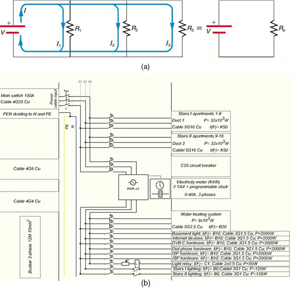
Figure 16.34 (a) Three resistors connected in parallel to a battery and the equivalent single or parallel resistance. (b) Electrical power setup in a house. Image from OpenStax College Physics 2e, CC-BY 4.0
Image Description
The image consists of two main diagrams related to electrical circuits and systems:
1. Diagram (a):
– This is a schematic representation of a parallel resistor circuit.
– A voltage source is shown on the left with a positive and negative terminal.
– Three resistors (R1, R2, R3) are connected in parallel with arrows indicating the direction of currents (I, I1, I2, I3) flowing through each resistor.
– An equation shows that these resistors can be simplified to a single equivalent resistor (Rp).
2. Diagram (b):
– This is a more complex schematic for an electrical distribution system.
– It includes detailed labeling for various components, such as:
– Main switch 100A connected with Cable 4G25 Cu.
– A PEN conductor dividing to N (neutral) and PE (protective earth).
– Components like C25 circuit breaker and electricity meter with TAX and a programmable clock for up to 40A, 3 phases.
– Connections to different areas and systems, such as stairs, ducts, basement, internet device, and lighting, each with specific cable and power specifications.
– Specific notation for power and cable type, such as 5G16 Cu and 3G1.5 Cu, denoting the number and type of conductors and their current or power capacity.
3. Additional Details:
– The distribution panel includes busbars, water heating system with 9×10^3 W power, and connections for various hardware systems.
The diagrams are labeled as (a) and (b) for reference and include comprehensive descriptions of the electrical components and their specifications.
To find an expression for the equivalent parallel resistance [latex]R_{\text{p}}[/latex], let us consider the currents that flow and how they are related to resistance. Since each resistor in the circuit has the full voltage, the currents flowing through the individual resistors are [latex]I_{1} = \frac{V}{R_{1}}[/latex], [latex]I_{2} = \frac{V}{R_{2}}[/latex], and [latex]I_{3} = \frac{V}{R_{3}}[/latex]. Conservation of charge implies that the total current [latex]I[/latex] produced by the source is the sum of these currents:
[latex]I = I_{1} + I_{2} + I_{3} .[/latex]
Substituting the expressions for the individual currents gives
[latex]I = \frac{V}{R_{1}} + \frac{V}{R_{2}} + \frac{V}{R_{3}} = V \left(\frac{1}{R_{1}} + \frac{1}{R_{2}} + \frac{1}{R_{3}}\right) .[/latex]
Note that Ohm’s law for the equivalent single resistance gives
[latex]I = \frac{V}{R_{p}} = V \left(\frac{1}{R_{p}}\right) .[/latex]
The terms inside the parentheses in the last two equations must be equal. Generalizing to any number of resistors, the total resistance [latex]R_{\text{p}}[/latex] of a parallel connection is related to the individual resistances by
[latex]\frac{1}{R_{p}} = \frac{1}{R_{1}} + \frac{1}{R_{2}} + \frac{1}{R_{. 3}} + . ...[/latex]
This relationship results in a total resistance [latex]R_{p}[/latex] that is less than the smallest of the individual resistances. (This is seen in the next example.) When resistors are connected in parallel, more current flows from the source than would flow for any of them individually, and so the total resistance is lower.
Example 16.12
Calculating Resistance, Current, Power Dissipation, and Power Output: Analysis of a Parallel Circuit
Let the voltage output of the battery and resistances in the parallel connection in Figure 16.34 be the same as the previously considered series connection: [latex]V = \text{12} . 0 \text{ V}[/latex], [latex]R_{1} = 1 . \text{00} \Omega[/latex], [latex]R_{2} = 6 . \text{00} \Omega[/latex], and [latex]R_{3} = \text{13} . 0 \Omega[/latex]. (a) What is the total resistance? (b) Find the total current. (c) Calculate the currents in each resistor, and show these add to equal the total current output of the source. (d) Calculate the power dissipated by each resistor. (e) Find the power output of the source, and show that it equals the total power dissipated by the resistors.
Strategy and Solution for (a)
The total resistance for a parallel combination of resistors is found using the equation below. Entering known values gives
[latex]\frac{1}{R_{p}} = \frac{1}{R_{1}} + \frac{1}{R_{2}} + \frac{1}{R_{3}} = \frac{1}{1 . \text{00} \Omega} + \frac{1}{6 . \text{00} \Omega} + \frac{1}{\text{13} . 0 \Omega} .[/latex]
Thus,
[latex]\frac{1}{R_{p}} = \frac{1.00}{\Omega} + \frac{0 . \text{1667}}{\Omega} + \frac{0 . \text{07692}}{\Omega} = \frac{1 . \text{2436}}{\Omega} .[/latex]
(Note that in these calculations, each intermediate answer is shown with an extra digit.)
We must invert this to find the total resistance [latex]R_{\text{p}}[/latex]. This yields
[latex]R_{\text{p}} = \frac{1}{1 . \text{2436}} \Omega = 0 . \text{8041 } \Omega .[/latex]
The total resistance with the correct number of significant digits is [latex]R_{\text{p}} = 0 . \text{804} \Omega .[/latex]
Discussion for (a)
[latex]R_{\text{p}}[/latex] is, as predicted, less than the smallest individual resistance.
Strategy and Solution for (b)
The total current can be found from Ohm’s law, substituting [latex]R_{\text{p}}[/latex] for the total resistance. This gives
[latex]I = \frac{V}{R_{\text{p}}} = \frac{\text{12}.\text{0 V}}{\text{0}.\text{8041 }\Omega} = \text{14} . \text{92 A} .[/latex]
Discussion for (b)
Current [latex]I[/latex] for each device is much larger than for the same devices connected in series (see the previous example). A circuit with parallel connections has a smaller total resistance than the resistors connected in series.
Strategy and Solution for (c)
The individual currents are easily calculated from Ohm’s law, since each resistor gets the full voltage. Thus,
[latex]I_{1} = \frac{V}{R_{1}} = \frac{\text{12} . 0 \text{ V}}{1 . \text{00 } \Omega} = \text{12} . 0 \text{ A} .[/latex]
Similarly,
[latex]I_{2} = \frac{V}{R_{2}} = \frac{\text{12} . 0 \text{ V}}{6 . \text{00 } \Omega} = 2 . \text{00} \text{ A}[/latex]
and
[latex]I_{3} = \frac{V}{R_{3}} = \frac{\text{12} . 0 \text{ V}}{\text{13} . \text{0 } \Omega} = 0 . \text{92} \text{ A} .[/latex]
Discussion for (c)
The total current is the sum of the individual currents:
[latex]I_{1} + I_{2} + I_{3} = \text{14} . \text{92} \text{ A} .[/latex]
This is consistent with conservation of charge.
Strategy and Solution for (d)
The power dissipated by each resistor can be found using any of the equations relating power to current, voltage, and resistance, since all three are known. Let us use [latex]P = \frac{V^{2}}{R}[/latex], since each resistor gets full voltage. Thus,
[latex]P_{1} = \frac{V^{2}}{R_{1}} = \frac{\left(\right. \text{12} . 0 \text{ V} \left.\right)^{2}}{1 . \text{00 } \Omega} = \text{144} \text{ W} .[/latex]
Similarly,
[latex]P_{2} = \frac{V^{2}}{R_{2}} = \frac{\left(\right. \text{12} . 0 \text{ V} \left.\right)^{2}}{6 . \text{00 } \Omega} = \text{24} . 0 \text{ W}[/latex]
and
[latex]P_{3} = \frac{V^{2}}{R_{3}} = \frac{\left(\right. \text{12} . 0 \text{ V} \left.\right)^{2}}{\text{13} . \text{0 } \Omega} = \text{11} . 1 \text{ W} .[/latex]
Discussion for (d)
The power dissipated by each resistor is considerably higher in parallel than when connected in series to the same voltage source.
Strategy and Solution for (e)
The total power can also be calculated in several ways. Choosing [latex]P = \text{IV}[/latex], and entering the total current, yields
[latex]P = \text{IV} = \left(\right. \text{14}.\text{92 A} \left.\right) \left(\right. \text{12}.\text{0 V} \left.\right) = \text{179 W} .[/latex]
Discussion for (e)
Total power dissipated by the resistors is also 179 W:
[latex]\begin{align*}P_{1} + P_{2} + P_{3} &= \text{144} \text{W} + \text{24} . 0 \text{W} + \text{11} . 1 \text{W}\\ &= \text{179} \text{W} .\end{align*}[/latex]
This is consistent with the law of conservation of energy.
Overall Discussion
Note that both the currents and powers in parallel connections are greater than for the same devices in series.
Major Features of Resistors in Parallel
- Parallel resistance is found from [latex]\frac{1}{R_{\text{p}}} = \frac{1}{R_{1}} + \frac{1}{R_{2}} + \frac{1}{R_{3}} + . . .[/latex], and it is smaller than any individual resistance in the combination.
- Each resistor in parallel has the same full voltage of the source applied to it. (Power distribution systems most often use parallel connections to supply the myriad devices served with the same voltage and to allow them to operate independently.)
- Parallel resistors do not each get the total current; they divide it.
Combinations of Series and Parallel
More complex connections of resistors are sometimes just combinations of series and parallel. These are commonly encountered, especially when wire resistance is considered. In that case, wire resistance is in series with other resistances that are in parallel.
Combinations of series and parallel can be reduced to a single equivalent resistance using the technique illustrated in Figure 16.35. Various parts are identified as either series or parallel, reduced to their equivalents, and further reduced until a single resistance is left. The process is more time consuming than difficult.
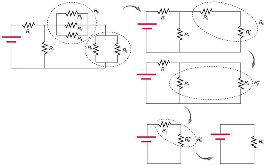
Figure 16.35 This combination of seven resistors has both series and parallel parts. Each is identified and reduced to an equivalent resistance, and these are further reduced until a single equivalent resistance is reached. Image from OpenStax College Physics 2e, CC-BY 4.0
Image Description
The image shows a series of electrical circuit diagrams demonstrating the process of simplifying a complex circuit. The steps are as follows:
1. Top Left Diagram:
– A circuit with a battery connected to various resistors, labeled R1, R7, and a group of parallel resistors Rp (comprising R2 and R3), and another set with R4 and R5. Resistor R6 is separate.
2. Top Right Diagram:
– The parallel resistors R2 and R3 have been combined into Rp, and R4 and R5 into R5′. The circuit now has R1, Rp, R7, and the combined R5 and R6 in parallel.
3. Middle Diagram:
– Resistor R6 is now combined with R5 into Rp”. The circuit is simplified further to include R1, R7, and Rp” in parallel.
4. Bottom Left Diagram:
– R1 and R7 remain in parallel with Rp’.
5. Bottom Right Diagram:
– Finally, the circuit is reduced to the battery connected to a single equivalent resistor R’eq.
Each diagram is connected with arrows, indicating the progression and simplification steps of combining resistors in parallel and series to reduce the circuit’s complexity.
The simplest combination of series and parallel resistance, shown in Figure 16.36, is also the most instructive, since it is found in many applications. For example, [latex]R_{1}[/latex] could be the resistance of wires from a car battery to its electrical devices, which are in parallel. [latex]R_{2}[/latex] and [latex]R_{3}[/latex] could be the starter motor and a passenger compartment light. We have previously assumed that wire resistance is negligible, but, when it is not, it has important effects, as the next example indicates.
Example 16.13
Calculating Resistance, [latex]\text{IR}[/latex] Drop, Current, and Power Dissipation: Combining Series and Parallel Circuits
Figure 16.36 shows the resistors from the previous two examples wired in a different way—a combination of series and parallel. We can consider [latex]R_{1}[/latex] to be the resistance of wires leading to [latex]R_{2}[/latex] and [latex]R_{3}[/latex]. (a) Find the total resistance. (b) What is the [latex]\text{IR}[/latex] drop in [latex]R_{1}[/latex]? (c) Find the current [latex]I_{2}[/latex] through [latex]R_{2}[/latex]. (d) What power is dissipated by [latex]R_{2}[/latex]?
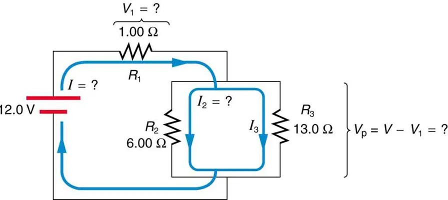
Figure 16.36 These three resistors are connected to a voltage source so that [latex]R_{2}[/latex] and [latex]R_{3}[/latex] are in parallel with one another and that combination is in series with [latex]R_{1}[/latex]. Image from OpenStax College Physics 2e, CC-BY 4.0
Image Description
The image is a diagram of an electrical circuit with two loops. The details are as follows:
- A battery on the left side labeled “12.0 V” is connected in series with three resistors: R1, R2, and R3.
- R1, at the top of the first loop, is labeled “1.00 Ω” and has its voltage drop labeled as V1 = ?.
- R2, at the bottom of the first loop, is labeled “6.00 Ω”.
- The first loop has a current labeled as I = ?.
- The second loop is nested inside the first and shares R2.
- R3, at the right side of the second loop, is labeled “13.0 Ω”.
- The second loop has a current labeled as I2 = ? in one section and I3 in another section of the loop.
- To the right of R3, there is an expression Vp = V – V1 = ?.
The diagram contains directional arrows indicating the direction of current flow in both loops.
Strategy and Solution for (a)
To find the total resistance, we note that [latex]R_{2}[/latex] and [latex]R_{3}[/latex] are in parallel and their combination [latex]R_{\text{p}}[/latex] is in series with [latex]R_{1}[/latex]. Thus the total (equivalent) resistance of this combination is
[latex]R_{\text{tot}} = R_{1} + R_{\text{p}} .[/latex]
First, we find [latex]R_{\text{p}}[/latex] using the equation for resistors in parallel and entering known values:
[latex]\frac{1}{R_{\text{p}}} = \frac{1}{R_{2}} + \frac{1}{R_{3}} = \frac{1}{6 . \text{00} \Omega} + \frac{1}{\text{13} . 0 \Omega} = \frac{0 . \text{2436}}{\Omega} .[/latex]
Inverting gives
[latex]R_{\text{p}} = \frac{1}{0 . \text{2436}} \Omega = 4 . \text{11} \Omega .[/latex]
So the total resistance is
[latex]R_{\text{tot}} = R_{1} + R_{\text{p}} = 1 . \text{00} \Omega + 4 . \text{11 } \Omega = 5 . \text{11 } \Omega .[/latex]
Discussion for (a)
The total resistance of this combination is intermediate between the pure series and pure parallel values ([latex]20.0 Ω[/latex] and [latex]0.804 Ω[/latex], respectively) found for the same resistors in the two previous examples.
Strategy and Solution for (b)
To find the [latex]\text{IR}[/latex] drop in [latex]R_{1}[/latex], we note that the full current [latex]I[/latex] flows through [latex]R_{1}[/latex]. Thus its [latex]\text{IR}[/latex] drop is
[latex]V_{1} = \text{IR}_{1} .[/latex]
We must find [latex]I[/latex] before we can calculate [latex]V_{1}[/latex]. The total current [latex]I[/latex] is found using Ohm’s law for the circuit. That is,
[latex]I = \frac{V}{R_{\text{tot}}} = \frac{\text{12} . 0 \text{ V}}{5 . \text{11 } \Omega} = 2 . \text{35} \text{A} .[/latex]
Entering this into the expression above, we get
[latex]V_{1} = \text{IR}_{1} = \left(\right. 2 . \text{35} \text{ A} \left.\right) \left(\right. 1 . \text{00} \Omega \left.\right) = 2 . \text{35} \text{ V} .[/latex]
Discussion for (b)
The voltage applied to [latex]R_{2}[/latex] and [latex]R_{3}[/latex] is less than the total voltage by an amount [latex]V_{1}[/latex]. When wire resistance is large, it can significantly affect the operation of the devices represented by [latex]R_{2}[/latex] and [latex]R_{3}[/latex].
Strategy and Solution for (c)
To find the current through [latex]R_{2}[/latex], we must first find the voltage applied to it. We call this voltage [latex]V_{\text{p}}[/latex], because it is applied to a parallel combination of resistors. The voltage applied to both [latex]R_{2}[/latex] and [latex]R_{3}[/latex] is reduced by the amount [latex]V_{1}[/latex], and so it is
[latex]V_{\text{p}} = V - V_{1} = \text{12} . 0 \text{ V} - 2 . \text{35} \text{ V} = 9 . \text{65} \text{ V} .[/latex]
Now the current [latex]I_{2}[/latex] through resistance [latex]R_{2}[/latex] is found using Ohm’s law:
[latex]I_{2} = \frac{V_{\text{p}}}{R_{2}} = \frac{9 . \text{65 V}}{6 . \text{00 } \Omega} = 1 . \text{61} \text{ A} .[/latex]
Discussion for (c)
The current is less than the 2.00 A that flowed through [latex]R_{2}[/latex] when it was connected in parallel to the battery in the previous parallel circuit example.
Strategy and Solution for (d)
The power dissipated by [latex]R_{2}[/latex] is given by
[latex]P_{2} = \left(\right. I_{2} \left.\right)^{2} R_{2} = \left(\right. 1 . \text{61} \text{ A} \left.\right)^{2} \left(\right. 6 . \text{00} \Omega \left.\right) = \text{15} . 5 \text{ W} .[/latex]
Discussion for (d)
The power is less than the 24.0 W this resistor dissipated when connected in parallel to the 12.0-V source.
Practical Implications
One implication of this last example is that resistance in wires reduces the current and power delivered to a resistor. If wire resistance is relatively large, as in a worn (or a very long) extension cord, then this loss can be significant. If a large current is drawn, the [latex]\text{IR}[/latex] drop in the wires can also be significant.
For example, when you are rummaging in the refrigerator and the motor comes on, the refrigerator light dims momentarily. Similarly, you can see the passenger compartment light dim when you start the engine of your car (although this may be due to resistance inside the battery itself).
What is happening in these high-current situations is illustrated in Figure 16.37. The device represented by [latex]R_{3}[/latex] has a very low resistance, and so when it is switched on, a large current flows. This increased current causes a larger [latex]\text{IR}[/latex] drop in the wires represented by [latex]R_{1}[/latex], reducing the voltage across the light bulb (which is [latex]R_{2}[/latex]), which then dims noticeably.
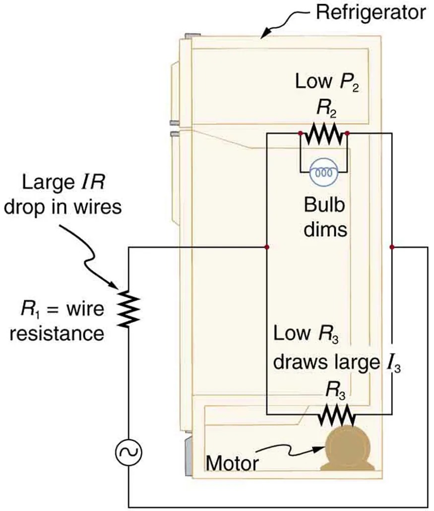
Figure 16.37 Why do lights dim when a large appliance is switched on? The answer is that the large current the appliance motor draws causes a significant [latex]\text{IR}[/latex] drop in the wires and reduces the voltage across the light. Image from OpenStax College Physics 2e, CC-BY 4.0
Image Description
The image is a diagram of a refrigerator’s electrical circuit, highlighting various components and their relationships:
- Refrigerator: The main object in the diagram, shown in profile.
- Internal Light Bulb: Positioned at the top inside the refrigerator, accompanied by a note that says “Bulb dims” due to low power (P2) across resistance (R2).
- Motor: Located at the bottom, marked by low resistance (R3) drawing a large current (I3).
- Wire Resistance: Denoted as R1, indicating a large IR drop in the wires.
- AC Power Source: Represented by a sine wave symbol.
Check Your Understanding
Can any arbitrary combination of resistors be broken down into series and parallel combinations? See if you can draw a circuit diagram of resistors that cannot be broken down into combinations of series and parallel.
Click for Solution
Solution
No, there are many ways to connect resistors that are not combinations of series and parallel, including loops and junctions.
Problem-Solving Strategies for Series and Parallel Resistors
- Draw a clear circuit diagram, labeling all resistors and voltage sources. This step includes a list of the knowns for the problem, since they are labeled in your circuit diagram.
- Identify exactly what needs to be determined in the problem (identify the unknowns). A written list is useful.
- Determine whether resistors are in series, parallel, or a combination of both series and parallel. Examine the circuit diagram to make this assessment. Resistors are in series if the same current must pass sequentially through them.
- Use the appropriate list of major features for series or parallel connections to solve for the unknowns. There is one list for series and another for parallel. If your problem has a combination of series and parallel, reduce it in steps by considering individual groups of series or parallel connections, as done in this module and the examples. Special note: When finding[latex]R \_{\text{p}}^{}[/latex], the reciprocal must be taken with care.
- Check to see whether the answers are reasonable and consistent. Units and numerical results must be reasonable. Total series resistance should be greater, whereas total parallel resistance should be smaller, for example. Power should be greater for the same devices in parallel compared with series, and so on.
