16.3 Resistance and Resistivity
Learning Objectives
By the end of this section, you will be able to:
- Explain the concept of resistivity.
- Use resistivity to calculate the resistance of specified configurations of material.
- Use the thermal coefficient of resistivity to calculate the change of resistance with temperature.
Material and Shape Dependence of Resistance
The resistance of an object depends on its shape and the material of which it is composed. The cylindrical resistor in Figure 16.10 is easy to analyze, and, by so doing, we can gain insight into the resistance of more complicated shapes. As you might expect, the cylinder’s electric resistance [latex]R[/latex] is directly proportional to its length [latex]L[/latex], similar to the resistance of a pipe to fluid flow. The longer the cylinder, the more collisions charges will make with its atoms. The greater the diameter of the cylinder, the more current it can carry (again similar to the flow of fluid through a pipe). In fact, [latex]R[/latex] is inversely proportional to the cylinder’s cross-sectional area [latex]A[/latex].
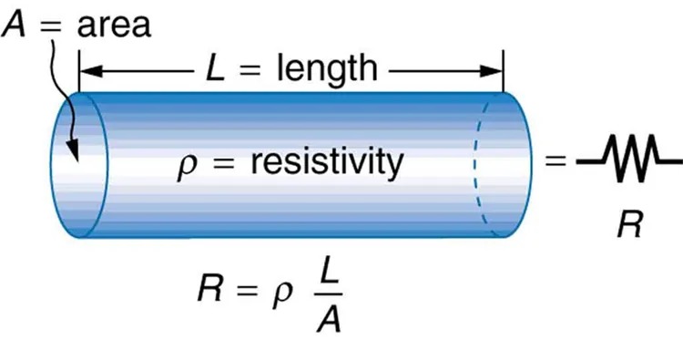
Figure 16.10 A uniform cylinder of length [latex]L[/latex] and cross-sectional area [latex]A[/latex]. Its resistance to the flow of current is similar to the resistance posed by a pipe to fluid flow. The longer the cylinder, the greater its resistance. The larger its cross-sectional area [latex]A[/latex], the smaller its resistance. Image from OpenStax College Physics 2e, CC-BY 4.0
Image Description
The image depicts a conceptual illustration of electrical resistivity in a cylindrical conductor. The following elements are shown in the image:
- A blue-colored cylinder representing a wire or conductor, which is oriented horizontally.
- Labels with arrows pointing to different parts of the cylinder:
- A = area: Arrow pointing to the cross-section of the cylinder, indicating its circular surface area.
- L = length: Arrow pointing parallel to the cylinder’s long axis, indicating its length.
- ρ = resistivity: Text near the cylinder, indicating the material property known as resistivity.
- An electrical resistor symbol is shown on the right end of the cylinder, labeled as R.
- Below the cylinder, the formula R = ρ (L/A) is presented, indicating the relationship between resistance (R), resistivity (ρ), length (L), and area (A).
For a given shape, the resistance depends on the material of which the object is composed. Different materials offer different resistance to the flow of charge. We define the resistivity [latex]\rho[/latex] of a substance so that the resistance [latex]R[/latex] of an object is directly proportional to [latex]\rho[/latex]. Resistivity [latex]\rho[/latex] is an intrinsic property of a material, independent of its shape or size. The resistance [latex]R[/latex] of a uniform cylinder of length [latex]L[/latex], of cross-sectional area [latex]A[/latex], and made of a material with resistivity [latex]\rho[/latex], is
[latex]R = \frac{ρL}{A} .[/latex]
Table 16.1 gives representative values of [latex]\rho[/latex]. The materials listed in the table are separated into categories of conductors, semiconductors, and insulators, based on broad groupings of resistivities. Conductors have the smallest resistivities, and insulators have the largest; semiconductors have intermediate resistivities. Conductors have varying but large free charge densities, whereas most charges in insulators are bound to atoms and are not free to move. Semiconductors are intermediate, having far fewer free charges than conductors, but having properties that make the number of free charges depend strongly on the type and amount of impurities in the semiconductor. These unique properties of semiconductors are put to use in modern electronics, as will be explored in later chapters.
| Material | Resistivity [latex]\rho[/latex] ( [latex]\Omega \cdot \text{m}[/latex] ) |
|---|---|
| Conductors | |
| Silver | [latex]1 . \text{59} \times \text{10}^{- 8}[/latex] |
| Copper | [latex]1 . \text{72} \times \text{10}^{- 8}[/latex] |
| Gold | [latex]2 . \text{44} \times \text{10}^{- 8}[/latex] |
| Aluminum | [latex]2 . \text{65} \times \text{10}^{- 8}[/latex] |
| Tungsten | [latex]5 . 6 \times \text{10}^{- 8}[/latex] |
| Iron | [latex]9 . \text{71} \times \text{10}^{- 8}[/latex] |
| Platinum | [latex]\text{10} . 6 \times \text{10}^{- 8}[/latex] |
| Steel | [latex]\text{20} \times \text{10}^{- 8}[/latex] |
| Lead | [latex]\text{22} \times \text{10}^{- 8}[/latex] |
| Manganin (Cu, Mn, Ni alloy) | [latex]\text{44} \times \text{10}^{- 8}[/latex] |
| Constantan (Cu, Ni alloy) | [latex]\text{49} \times \text{10}^{- 8}[/latex] |
| Mercury | [latex]\text{96} \times \text{10}^{- 8}[/latex] |
| Nichrome (Ni, Fe, Cr alloy) | [latex]\text{100} \times \text{10}^{- 8}[/latex] |
| Semiconductors[1] | |
| Carbon (pure) | [latex]\text{3}.\text{5} \times \text{10}^{–5}[/latex] |
| Carbon | [latex]\left(\right. 3.5 - \text{60} \left.\right) \times \text{10}^{–5}[/latex] |
| Germanium (pure) | [latex]\text{600} \times \text{10}^{- 3}[/latex] |
| Germanium | [latex]\left(\right. 1 - \text{600} \left.\right) \times \text{10}^{- 3}[/latex] |
| Silicon (pure) | [latex]\text{2300}[/latex] |
| Silicon | [latex]\text{0}.\text{1}–\text{2300}[/latex] |
| Insulators | |
| Amber | [latex]5 \times \text{10}^{\text{14}}[/latex] |
| Glass | [latex]\text{10}^{9} - \text{10}^{\text{14}}[/latex] |
| Lucite | [latex]>\text{10}^{\text{13}}[/latex] |
| Mica | [latex]\text{10}^{\text{11}} - \text{10}^{\text{15}}[/latex] |
| Quartz (fused) | [latex]\text{75} \times \text{10}^{\text{16}}[/latex] |
| Rubber (hard) | [latex]\text{10}^{\text{13}} - \text{10}^{\text{16}}[/latex] |
| Sulfur | [latex]\text{10}^{\text{15}}[/latex] |
| Teflon | [latex]>\text{10}^{\text{13}}[/latex] |
| Wood | [latex]\text{10}^{8} - \text{10}^{\text{11}}[/latex] |
Example 16.5
Calculating Resistor Diameter: A Headlight Filament
A car headlight filament is made of tungsten and has a cold resistance of [latex]0 . \text{350} \Omega[/latex]. If the filament is a cylinder 4.00 cm long (it may be coiled to save space), what is its diameter?
Strategy
We can rearrange the equation [latex]R = \frac{ρL}{A}[/latex] to find the cross-sectional area [latex]A[/latex] of the filament from the given information. Then its diameter can be found by assuming it has a circular cross-section.
Solution
The cross-sectional area, found by rearranging the expression for the resistance of a cylinder given in [latex]R = \frac{ρL}{A}[/latex], is
[latex]A = \frac{ρL}{R} .[/latex]
Substituting the given values, and taking [latex]\rho[/latex] from Table 16.1, yields
[latex]\begin{eqnarray*}A & = & \frac{\left(\right. 5.6 \times \text{10}^{–8} \Omega \cdot \text{m} \left.\right) \left(\right. 4.00 \times \text{10}^{–2} \text{ m} \left.\right)}{\text{0}.\text{350 } \Omega} \\ & = & \text{ 6}.\text{40} \times \text{10}^{–9} \text{ m}^{2} .\end{eqnarray*}[/latex]
The area of a circle is related to its diameter [latex]D[/latex] by
[latex]A = \frac{πD^{2}}{4} .[/latex]
Solving for the diameter [latex]D[/latex], and substituting the value found for [latex]A[/latex], gives
[latex]\begin{eqnarray*}D & = & \text{ 2} \left(\frac{A}{\pi}\right)^{\frac{1}{2}} = \text{ 2} \left(\frac{6.40 \times \text{10}^{–9} \text{m}^{2}}{3.14}\right)^{\frac{1}{2}} \\ & = & 9.0 \times \text{10}^{–5} \text{m}.\end{eqnarray*}[/latex]
Discussion
The diameter is just under a tenth of a millimeter. It is quoted to only two digits, because [latex]\rho[/latex] is known to only two digits.
Temperature Variation of Resistance
The resistivity of all materials depends on temperature. Some even become superconductors (zero resistivity) at very low temperatures. (See Figure 16.11.) Conversely, the resistivity of conductors increases with increasing temperature. Since the atoms vibrate more rapidly and over larger distances at higher temperatures, the electrons moving through a metal make more collisions, effectively making the resistivity higher. Over relatively small temperature changes (about [latex]\text{100}º \text{C}[/latex] or less), resistivity [latex]\rho[/latex] varies with temperature change [latex]Δ T[/latex] as expressed in the following equation
[latex]\rho = \rho_{0} \left(\right. \text{1 } + \alpha Δ T \left.\right) ,[/latex]
where [latex]\rho_{0}[/latex] is the original resistivity and [latex]\alpha[/latex] is the temperature coefficient of resistivity. (See the values of [latex]\alpha[/latex] in Table 16.2 below.) For larger temperature changes, [latex]\alpha[/latex] may vary or a nonlinear equation may be needed to find [latex]\rho[/latex]. Note that [latex]\alpha[/latex] is positive for metals, meaning their resistivity increases with temperature. Some alloys have been developed specifically to have a small temperature dependence. Manganin (which is made of copper, manganese and nickel), for example, has [latex]\alpha[/latex] close to zero (to three digits on the scale in Table 16.2), and so its resistivity varies only slightly with temperature. This is useful for making a temperature-independent resistance standard, for example.
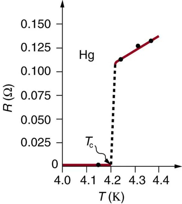
Figure 16.11 The resistance of a sample of mercury is zero at very low temperatures—it is a superconductor up to about 4.2 K. Above that critical temperature, its resistance makes a sudden jump and then increases nearly linearly with temperature. Image from OpenStax College Physics 2e, CC-BY 4.0
Image Description
The image is a graph showing the relationship between resistance (R) in ohms (Ω) and temperature (T) in Kelvin (K) for Mercury (Hg). The x-axis represents temperature, ranging from 4.0 K to 4.4 K. The y-axis represents resistance, ranging from 0 to 0.150 Ω.
There is a red line on the graph that illustrates the data, which is marked with black dots at key points. The graph shows a horizontal line near zero resistance from 4.0 K to approximately 4.15 K, indicating zero resistance in this temperature range.
At around 4.15 K, marked as Tc, there is a sudden upward change, where the resistance sharply increases. A dashed line is used to connect this jump. After the transition, the red line continues upward with increasing resistance as temperature increases.
| Material | Coefficient [latex]\alpha[/latex](1/°C)[2] |
|---|---|
| Conductors | |
| Silver | [latex]3 . 8 \times \text{10}^{- 3}[/latex] |
| Copper | [latex]3 . 9 \times \text{10}^{- 3}[/latex] |
| Gold | [latex]3 . 4 \times \text{10}^{- 3}[/latex] |
| Aluminum | [latex]3 . 9 \times \text{10}^{- 3}[/latex] |
| Tungsten | [latex]4 . 5 \times \text{10}^{- 3}[/latex] |
| Iron | [latex]5 . 0 \times \text{10}^{- 3}[/latex] |
| Platinum | [latex]3 . \text{93} \times \text{10}^{- 3}[/latex] |
| Lead | [latex]3 . 9 \times \text{10}^{- 3}[/latex] |
| Manganin (Cu, Mn, Ni alloy) | [latex]0 . \text{000} \times \text{10}^{- 3}[/latex] |
| Constantan (Cu, Ni alloy) | [latex]0 . \text{002} \times \text{10}^{- 3}[/latex] |
| Mercury | [latex]0 . \text{89} \times \text{10}^{- 3}[/latex] |
| Nichrome (Ni, Fe, Cr alloy) | [latex]0 . 4 \times \text{10}^{- 3}[/latex] |
| Semiconductors | |
| Carbon (pure) | [latex]- 0 . 5 \times \text{10}^{- 3}[/latex] |
| Germanium (pure) | [latex]- \text{50} \times \text{10}^{- 3}[/latex] |
| Silicon (pure) | [latex]- \text{70} \times \text{10}^{- 3}[/latex] |
The resistance of an object also depends on temperature, since [latex]R_{0}[/latex] is directly proportional to [latex]\rho[/latex]. For a cylinder we know [latex]R = ρL / A[/latex], and so, if [latex]L[/latex] and [latex]A[/latex] do not change greatly with temperature, [latex]R[/latex] will have the same temperature dependence as [latex]\rho[/latex]. (Examination of the coefficients of linear expansion shows them to be about two orders of magnitude less than typical temperature coefficients of resistivity, and so the effect of temperature on [latex]L[/latex] and [latex]A[/latex] is about two orders of magnitude less than on [latex]\rho[/latex].) Thus,
[latex]R = R_{0} \left(\right. \text{1 } + \alpha Δ T \left.\right)[/latex]
is the temperature dependence of the resistance of an object, where [latex]R_{0}[/latex] is the original resistance and [latex]R[/latex] is the resistance after a temperature change [latex]Δ T[/latex]. Numerous thermometers are based on the effect of temperature on resistance. (See Figure 16.12.) One of the most common is the thermistor, a semiconductor crystal with a strong temperature dependence, the resistance of which is measured to obtain its temperature. The device is small, so that it quickly comes into thermal equilibrium with the part of a person it touches.
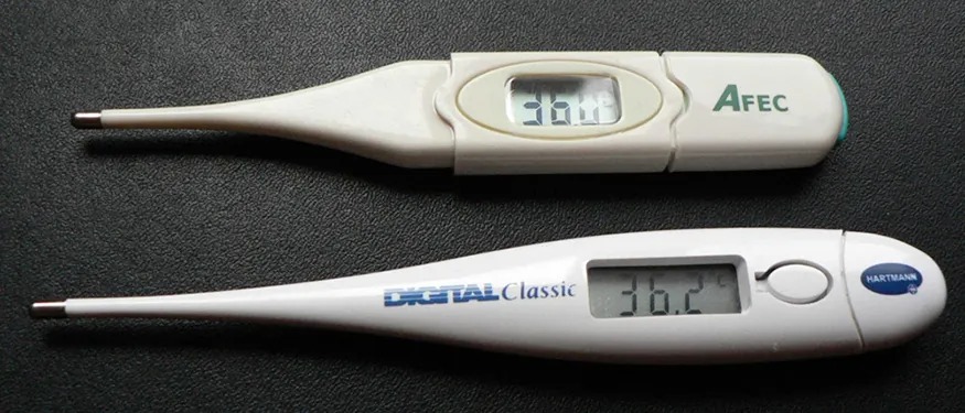
Figure 16.12 These familiar thermometers are based on the automated measurement of a thermistor’s temperature-dependent resistance. Image from OpenStax College Physics 2e, CC-BY 4.0
Example 16.6
Calculating Resistance: Hot-Filament Resistance
Although caution must be used in applying [latex]\rho = \rho_{0} \left(\right. \text{1 } + \alpha Δ T \left.\right)[/latex] and [latex]R = R_{0} \left(\right. \text{1 } + \alpha Δ T \left.\right)[/latex] for temperature changes greater than [latex]\text{100}º \text{C}[/latex], for tungsten the equations work reasonably well for very large temperature changes. What, then, is the resistance of the tungsten filament in the previous example if its temperature is increased from room temperature ([latex]\text{20}º\text{C}[/latex]) to a typical operating temperature of [latex]\text{2850}º \text{C}[/latex]?
Strategy
This is a straightforward application of [latex]R = R_{0} \left(\right. \text{1 } + \alpha Δ T \left.\right)[/latex], since the original resistance of the filament was given to be [latex]R_{0} = 0 . \text{350 }\Omega[/latex], and the temperature change is [latex]Δ T = \text{2830}º \text{C}[/latex].
Solution
The hot resistance [latex]R[/latex] is obtained by entering known values into the above equation:
[latex]\begin{eqnarray*}R & = & R_{0} \left(\right. 1 + \alpha Δ T \left.\right) \\ & = & \left(\right. 0 . \text{350 }\Omega \left.\right) \left[\right. \text{1 } + \left(\right. 4.5 \times \text{10}^{–3} / º\text{C} \left.\right) \left(\right. \text{2830}º \text{C} \left.\right) \left]\right. \\ & = & \text{ 4}.\text{8 }\Omega.\end{eqnarray*}[/latex]
Discussion
This value is consistent with the headlight resistance example in 16.2 Ohm’s Law: Resistance and Simple Circuits.
PhET Explorations
Resistance in a Wire
Learn about the physics of resistance in a wire. Change its resistivity, length, and area to see how they affect the wire’s resistance. The sizes of the symbols in the equation change along with the diagram of a wire.
