13.1 Hooke’s Law: Stress and Strain Revisited
Learning Objectives
By the end of this section, you will be able to:
- Explain Newton’s third law of motion with respect to stress and deformation.
- Describe the restoration of force and displacement.
- Calculate the energy in Hooke’s Law of deformation, and the stored energy in a spring.
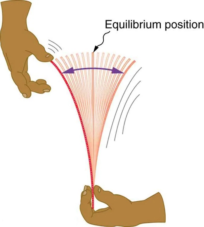
Figure 13.2 When displaced from its vertical equilibrium position, this plastic ruler oscillates back and forth because of the restoring force opposing displacement. When the ruler is on the left, there is a force to the right, and vice versa. Image from OpenStax College Physics 2e, CC-BY 4.0
Image Description
The image depicts an illustration of a hand holding a flexible object, like a ruler, being bent. The top hand appears poised above the ruler, while the bottom hand holds it tightly and bends it backwards, creating tension. The ruler bends in an arc, exhibiting several curved lines that indicate its motion and vibration. There are arrows showing the direction of motion towards an “equilibrium position” label, which is central to the bending arc. The arrangement suggests oscillation or vibration as the ruler is released and moves back and forth around the equilibrium position. The background is plain, emphasizing the focus on the hands and the ruler.
Newton’s first law implies that an object oscillating back and forth is experiencing forces. Without force, the object would move in a straight line at a constant speed rather than oscillate. Consider, for example, plucking a plastic ruler to the left as shown in Figure 13.2. The deformation of the ruler creates a force in the opposite direction, known as a restoring force. Once released, the restoring force causes the ruler to move back toward its stable equilibrium position, where the net force on it is zero. However, by the time the ruler gets there, it gains momentum and continues to move to the right, producing the opposite deformation. It is then forced to the left, back through equilibrium, and the process is repeated until dissipative forces dampen the motion. These forces remove mechanical energy from the system, gradually reducing the motion until the ruler comes to rest.
The simplest oscillations occur when the restoring force is directly proportional to displacement. When stress and strain were covered in Newton’s Third Law of Motion, the name was given to this relationship between force and displacement was Hooke’s law:
[latex]F = - \text{kx}.[/latex]
Here, [latex]F[/latex] is the restoring force, [latex]x[/latex] is the displacement from equilibrium or deformation, and [latex]k[/latex] is a constant related to the difficulty in deforming the system. The minus sign indicates the restoring force is in the direction opposite to the displacement.
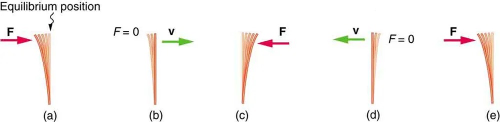
Figure 13.3 (a) The plastic ruler has been released, and the restoring force is returning the ruler to its equilibrium position. (b) The net force is zero at the equilibrium position, but the ruler has momentum and continues to move to the right. (c) The restoring force is in the opposite direction. It stops the ruler and moves it back toward equilibrium again. (d) Now the ruler has momentum to the left. (e) In the absence of damping (caused by frictional forces), the ruler reaches its original position. From there, the motion will repeat itself. Image from OpenStax College Physics 2e, CC-BY 4.0
Image Description
The image illustrates the stages of a plucked object, likely a cantilever or beam, undergoing oscillation from an initial displacement due to a force, labeled F. There are five distinct positions, labeled from (a) to (e):
- (a): The object is bent to the left by a force (F) shown with a pink arrow pointing left. The object is displaced from its equilibrium position, which is marked above.
- (b): The force (F) is zero, and the object is returning to its equilibrium position. A green arrow indicates the velocity (v) going to the right.
- (c): The object passes through the equilibrium position. A force (F) is applied from the right with a pink arrow.
- (d): The object continues to the right, and the velocity (v) is depicted with a green arrow pointing left. The force (F) is zero.
- (e): The object bends to the right under the influence of a force (F) shown with a pink arrow pointing right.
The force constant [latex]k[/latex] is related to the rigidity (or stiffness) of a system—the larger the force constant, the greater the restoring force, and the stiffer the system. The units of [latex]k[/latex] are newtons per meter (N/m). For example, [latex]k[/latex] is directly related to Young’s modulus when we stretch a string. Figure 13.4 shows a graph of the absolute value of the restoring force versus the displacement for a system that can be described by Hooke’s law—a simple spring in this case. The slope of the graph equals the force constant [latex]k[/latex] in newtons per meter. A common physics laboratory exercise is to measure restoring forces created by springs, determine if they follow Hooke’s law, and calculate their force constants if they do.
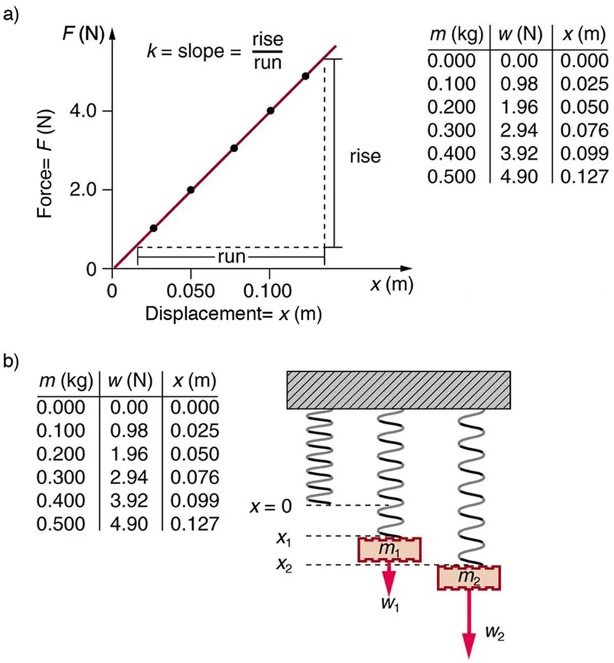
Figure 13.4 (a) A graph of absolute value of the restoring force versus displacement is displayed. The fact that the graph is a straight line means that the system obeys Hooke’s law. The slope of the graph is the force constant [latex]k[/latex]. (b) The data in the graph were generated by measuring the displacement of a spring from equilibrium while supporting various weights. The restoring force equals the weight supported, if the mass is stationary. Image from OpenStax College Physics 2e, CC-BY 4.0
Image Description
The image consists of two parts labeled a) and b). Below is the description for each part.
a) This section depicts a line graph and a table. The graph shows the relationship between Force (F) in Newtons plotted on the y-axis and Displacement (x) in meters on the x-axis. A red line with plotted points rises diagonally, indicating a linear relationship. Text annotations explain that the slope (k) is calculated as the rise divided by the run. Next to the graph is a table with three columns representing mass (m), weight (w), and displacement (x).
| m (kg) | w (N) | x (m) |
|---|---|---|
| 0.000 | 0.00 | 0.000 |
| 0.100 | 0.98 | 0.025 |
| 0.200 | 1.96 | 0.050 |
| 0.300 | 2.94 | 0.076 |
| 0.400 | 3.92 | 0.099 |
| 0.500 | 4.90 | 0.127 |
b) The section includes a similar table as in part a) and a diagram of two vertical springs fixed to a horizontal surface. The first spring is labeled with mass m1 and weight W1, with displacement levels x1 and x2 marked. The second spring, which is identical in form to the first, is similarly labeled with mass m2 and weight W2. Each spring extends under a mass, visualized as rectangles hanging from the spring, with forces marked by downward arrows.
Example 13.1
How Stiff Are Car Springs?

What is the force constant for the suspension system of a car that settles 1.20 cm when an 80.0-kg person gets in?
Strategy
Consider the car to be in its equilibrium position [latex]x = 0[/latex] before the person gets in. The car then settles down 1.20 cm, which means it is displaced to a position [latex]x = - 1 . \text{20} \times \text{10}^{- 2} \text{m}[/latex]. At that point, the springs supply a restoring force [latex]F[/latex] equal to the person’s weight [latex]w = \text{mg} = \left(\text{80} . 0 \text{ kg}\right) \left(9 . \text{80} \text{m}/\text{s}^{2}\right) = \text{784} \text{N}[/latex]. We take this force to be [latex]F[/latex] in Hooke’s law. Knowing [latex]F[/latex] and [latex]x[/latex], we can then solve the force constant [latex]k[/latex].
Solution
- Solve Hooke’s law, [latex]F = - \text{kx}[/latex], for [latex]k[/latex]:
[latex]k = - \frac{F}{x} .[/latex]
13.2Substitute known values and solve [latex]k[/latex]:
[latex]\begin{eqnarray*}k & = & - \frac{\text{784} \text{ N}}{- 1 . \text{20} \times \text{10}^{- 2} \text{ m}} \\ & = & 6 . \text{53} \times \text{10}^{4} \text{ N}/\text{m} .\end{eqnarray*}[/latex]
13.3
Discussion
Note that [latex]F[/latex] and [latex]x[/latex] have opposite signs because they are in opposite directions—the restoring force is up, and the displacement is down. Also, note that the car would oscillate up and down when the person got in if it were not for damping (due to frictional forces) provided by shock absorbers. Bouncing cars are a sure sign of bad shock absorbers.
Energy in Hooke’s Law of Deformation
In order to produce a deformation, work must be done. That is, a force must be exerted through a distance, whether you pluck a guitar string or compress a car spring. If the only result is deformation, and no work goes into thermal, sound, or kinetic energy, then all the work is initially stored in the deformed object as some form of potential energy. The potential energy stored in a spring is [latex]\text{PE}_{\text{s}} = \frac{1}{2} kx^{2}[/latex]. Here, we generalize the idea to elastic potential energy for a deformation of any system that can be described by Hooke’s law. Hence,
[latex]\text{PE}_{\text{el}} = \frac{1}{2} kx^{2} ,[/latex]
where [latex]\text{PE}_{\text{el}}[/latex] is the elastic potential energy stored in any deformed system that obeys Hooke’s law and has a displacement [latex]x[/latex] from equilibrium and a force constant [latex]k[/latex].
It is possible to find the work done in deforming a system in order to find the energy stored. This work is performed by an applied force [latex]F_{\text{app}}[/latex]. The applied force is exactly opposite to the restoring force (action-reaction), and so [latex]F_{\text{app}} = \text{kx}[/latex]. Figure 13.6 shows a graph of the applied force versus deformation [latex]x[/latex] for a system that can be described by Hooke’s law. Work done on the system is force multiplied by distance, which equals the area under the curve or [latex]\left(\right. 1 / 2 \left.\right) kx^{2}[/latex](Method A in the figure). Another way to determine the work is to note that the force increases linearly from 0 to [latex]kx[/latex], so that the average force is [latex]\left(\right. 1 / 2 \left.\right) kx[/latex], the distance moved is [latex]x[/latex], and thus [latex]W = F_{\text{app}} d = \left[\right. \left(\right. 1 / 2 \left.\right) \text{kx} \left]\right. \left(\right. x \left.\right) = \left(\right. 1 / 2 \left.\right) kx^{2}[/latex] (Method B in the figure).
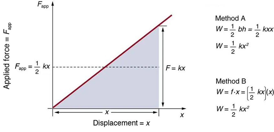
Figure 13.6 A graph of applied force versus distance for the deformation of a system that can be described by Hooke’s law is displayed. The work done on the system equals the area under the graph or the area of the triangle, which is half its base multiplied by its height, or [latex]W = \left(\right. 1 / 2 \left.\right) kx^{2}[/latex]. Image from OpenStax College Physics 2e, CC-BY 4.0
Image Description
The image depicts a graph and mathematical formulas illustrating the concept of work done in physics regarding applied force and displacement.
Graph Description:
- Axes: The graph has two axes; the vertical axis is labeled “Applied force = Fapp” and the horizontal axis is labeled “Displacement = x”.
- Line and Area: There is a red line extending from the origin, showing a linear increase in force with displacement. A shaded triangular area lies under this line, bounded by the x-axis and the vertical dashed line labeled “F = kx”.
- Label: On the vertical axis, a point is marked with the label “Fapp = 1/2 kx”.
- Triangle: The shaded triangle represents the work done, calculated as the area under the force-displacement curve.
Formulas on the Right:
- Two methods for calculating work are shown:
- Method A:
- W = 1/2 bh = 1/2 kxx
- W = 1/2 kx2
- Method B:
- W = f · x = [1/2 kx](x)
- W = 1/2 kx2
Example 13.2
Calculating Stored Energy: A Toy Gun Spring
We can use a toy gun’s spring mechanism to ask and answer two simple questions: (a) How much energy is stored in the spring of a toy gun that has a force constant of 50.0 N/m and is compressed 0.150 m? (b) If you neglect friction and the mass of the spring, at what speed will a 2.00-g projectile be ejected from the gun?
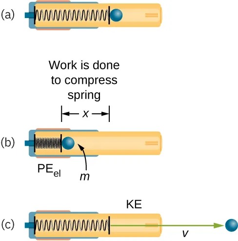
Figure 13.7 (a) In this image of the gun, the spring is uncompressed before being cocked. (b) The spring has been compressed a distance [latex]x[/latex], and the projectile is in place. (c) When released, the spring converts elastic potential energy [latex]\text{PE}_{\text{el}}[/latex] into kinetic energy. Image from OpenStax College Physics 2e, CC-BY 4.0
Image Description
The image is a diagram illustrating the conversion of potential energy to kinetic energy using a compressed spring and a ball. It consists of three parts:
- (a) A spring inside a cylindrical tube is shown in a relaxed state, with a blue ball resting against the uncompressed end of the spring.
- (b) The spring is now compressed, and the ball is closer to the compression point. An arrow labeled “Work is done to compress spring” is pointing down with a label “x“, representing the compression distance. The compressed spring has a label “PEel” indicating elastic potential energy, and the ball is labeled with “m” for mass.
- (c) The spring is released, pushing the ball out of the tube. The ball is moving to the right with velocity “v“, and an arrow labeled “KE” represents kinetic energy.
Strategy for a
(a): The energy stored in the spring can be found directly from elastic potential energy equation, because [latex]k[/latex] and [latex]x[/latex] are given.
Solution for a
Entering the given values for [latex]k[/latex] and [latex]x[/latex] yields
[latex]\begin{eqnarray*}\text{PE}_{\text{el}} & = & \frac{1}{2} kx^{2} = \frac{1}{2} \left(\text{50} . 0 \text{ N}/\text{m}\right) \left(0 . \text{150} \text{ m}\right)^{2} = 0 . \text{563} \text{N} \cdot \text{m} \\ & = & 0 . \text{563} \text{J}\end{eqnarray*}[/latex]
Strategy for b
Because there is no friction, the potential energy is converted entirely into kinetic energy. The expression for kinetic energy can be solved for the projectile’s speed.
Solution for b
- Identify known quantities:
[latex]\text{KE }_{\text{f }} = \text{PE }_{\text{el }} or 1 / 2 \mathit{mv}^{2} = \left(\right. 1 / 2 \left.\right) \mathit{kx}^{2} = \text{PE}_{el} = 0 . \text{563} \text{J}[/latex]
13.6 - Solve for [latex]v[/latex]:
[latex]v = \left[\frac{2 \text{PE}_{\text{el}}}{m}\right]^{1 / 2} = \left[\frac{2 \left(0.563 \text{ J}\right)}{0.002 \text{ kg}}\right]^{1 / 2} = \text{23}.\text{7} \left(\text{J}/\text{kg}\right)^{1 / 2}[/latex]
13.7 - Convert units: [latex]23.7 \text{ m } / \text{s }[/latex]
Discussion
(a) and (b): This projectile speed is impressive for a toy gun (more than 80 km/h). The numbers in this problem seem reasonable. The force needed to compress the spring is small enough for an adult to manage, and the energy imparted to the dart is small enough to limit the damage it might do, especially because the darts in many of these guns are made of soft material with a rubber tip. Yet, the speed of the dart is great enough for it to travel an acceptable distance.
Check Your Understanding
Envision holding the end of a ruler with one hand and deforming it with the other. When you let go, you can see the oscillations of the ruler. In what way could you modify this simple experiment to increase the rigidity of the system?
Click for Solution
Solution
You could hold the ruler at its midpoint so that the part of the ruler that oscillates is half as long as in the original experiment.
Check Your Understanding
If you apply a deforming force on an object and let it come to equilibrium, what happened to the work you did on the system?
Click for Solution
Solution
It was stored in the object as potential energy.
