14.7 Ultrasound
Learning Objectives
By the end of this section, you will be able to:
- Define acoustic impedance and intensity reflection coefficient.
- Describe medical and other uses of ultrasound technology.
- Calculate acoustic impedance using density values and the speed of ultrasound.
- Calculate the velocity of a moving object using Doppler-shifted ultrasound.
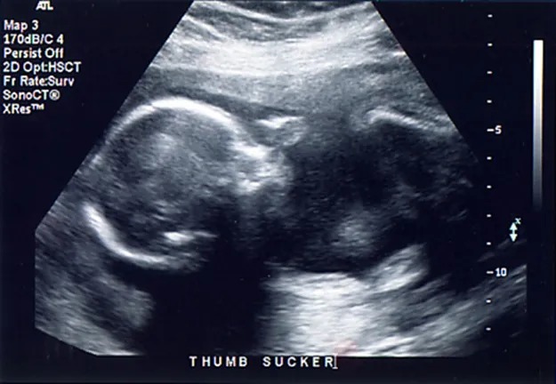
Figure 14.40 Ultrasound is used in medicine to painlessly and noninvasively monitor patient health and diagnose a wide range of disorders. Image from OpenStax College Physics 2e, CC-BY 4.0
Any sound with a frequency above 20,000 Hz (or 20 kHz)—that is, above the highest audible frequency—is defined to be ultrasound. In practice, it is possible to create ultrasound frequencies up to more than a gigahertz. (Higher frequencies are difficult to create; furthermore, they propagate poorly because they are very strongly absorbed.) Ultrasound has a tremendous number of applications, which range from burglar alarms to use in cleaning delicate objects to the guidance systems of bats. We begin our discussion of ultrasound with some of its applications in medicine, in which it is used extensively both for diagnosis and for therapy.
Characteristics of Ultrasound
The characteristics of ultrasound, such as frequency and intensity, are wave properties common to all types of waves. Ultrasound also has a wavelength that limits the fineness of detail it can detect. This characteristic is true of all waves. We can never observe details significantly smaller than the wavelength of our probe; for example, we will never see individual atoms with visible light, because the atoms are so small compared with the wavelength of light.
Ultrasound in Medical Therapy
Ultrasound, like any wave, carries energy that can be absorbed by the medium carrying it, producing effects that vary with intensity. When focused to intensities of [latex]\text{10}^{\text{3}}[/latex] to [latex]\text{10}^{\text{5}}[/latex] [latex]\text{W}/\text{m}^{\text{2}}[/latex], ultrasound can be used to shatter gallstones or pulverize cancerous tissue in surgical procedures. (See Figure 14.41.) Intensities this great can damage individual cells, variously causing their protoplasm to stream inside them, altering their permeability, or rupturing their walls through cavitation. Cavitation is the creation of vapor cavities in a fluid—the longitudinal vibrations in ultrasound alternatively compress and expand the medium, and at sufficient amplitudes the expansion separates molecules. Most cavitation damage is done when the cavities collapse, producing even greater shock pressures.
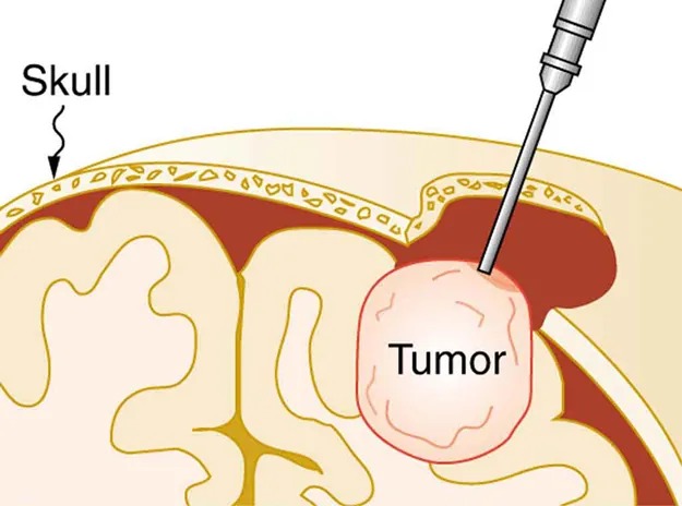
Figure 14.41 The tip of this small probe oscillates at 23 kHz with such a large amplitude that it pulverizes tissue on contact. The debris is then aspirated. The speed of the tip may exceed the speed of sound in tissue, thus creating shock waves and cavitation, rather than a smooth simple harmonic oscillator–type wave. Image from OpenStax College Physics 2e, CC-BY 4.0
Image Description
The image is an illustrated cross-section of part of the brain and skull, highlighting the presence of a tumor. The skull is labeled and depicted as a thick outer layer. Beneath the skull, the brain is visible with its intricate folds. A tumor is labeled, shown pushing against the brain tissue. A surgical tool is illustrated as approaching the tumor, indicating a medical procedure. The style is schematic, with each anatomical part clearly distinguished by different colors and labels for educational purposes.
Most of the energy carried by high-intensity ultrasound in tissue is converted to thermal energy. In fact, intensities of [latex]\text{10}^{3}[/latex] to [latex]\text{10}^{4} \text{W}/\text{m}^{2}[/latex] are commonly used for deep-heat treatments called ultrasound diathermy. Frequencies of 0.8 to 1 MHz are typical. In both athletics and physical therapy, ultrasound diathermy is most often applied to injured or overworked muscles to relieve pain and improve flexibility. Skill is needed by the therapist to avoid “bone burns” and other tissue damage caused by overheating and cavitation, sometimes made worse by reflection and focusing of the ultrasound by joint and bone tissue.
In some instances, you may encounter a different decibel scale, called the sound pressure level, when ultrasound travels in water or in human and other biological tissues. We shall not use the scale here, but it is notable that numbers for sound pressure levels range 60 to 70 dB higher than you would quote for [latex]\beta[/latex], the sound intensity level used in this text. Should you encounter a sound pressure level of 220 decibels, then, it is not an astronomically high intensity, but equivalent to about 155 dB—high enough to destroy tissue, but not as unreasonably high as it might seem at first.
Ultrasound in Medical Diagnostics
When used for imaging, ultrasonic waves are emitted from a transducer, a crystal exhibiting the piezoelectric effect (the expansion and contraction of a substance when a voltage is applied across it, causing a vibration of the crystal). These high-frequency vibrations are transmitted into any tissue in contact with the transducer. Similarly, if a pressure is applied to the crystal (in the form of a wave reflected off tissue layers), a voltage is produced which can be recorded. The crystal therefore acts as both a transmitter and a receiver of sound. Ultrasound is also partially absorbed by tissue on its path, both on its journey away from the transducer and on its return journey. From the time between when the original signal is sent and when the reflections from various boundaries between media are received, (as well as a measure of the intensity loss of the signal), the nature and position of each boundary between tissues and organs may be deduced.
Reflections at boundaries between two different media occur because of differences in a characteristic known as the acoustic impedance [latex]Z[/latex] of each substance. Impedance is defined as
[latex]Z = \rho\text{v} ,[/latex]
where [latex]\rho[/latex] is the density of the medium (in [latex]kg/m^{3}[/latex]) and [latex]v[/latex] is the speed of sound through the medium (in m/s). The units for [latex]Z[/latex] are therefore [latex]kg/(m^{2} \cdot \text{s})[/latex].
Table 14.5 shows the density and speed of sound through various media (including various soft tissues) and the associated acoustic impedances. Note that the acoustic impedances for soft tissue do not vary much but that there is a big difference between the acoustic impedance of soft tissue and air and also between soft tissue and bone.
The intensity reflection coefficient [latex]a[/latex] is defined as the ratio of the intensity of the reflected wave relative to the incident (transmitted) wave. This statement can be written mathematically as
[latex]a = \frac{\left(Z_{2} - Z_{1}\right)^{2}}{\left(Z_{1} + Z_{2}\right)^{2}} ,[/latex]
where [latex]Z_{1}[/latex] and [latex]Z_{2}[/latex] are the acoustic impedances of the two media making up the boundary. A reflection coefficient of zero (corresponding to total transmission and no reflection) occurs when the acoustic impedances of the two media are the same. An impedance “match” (no reflection) provides an efficient coupling of sound energy from one medium to another. The image formed in an ultrasound is made by tracking reflections (as shown in Figure 14.42) and mapping the intensity of the reflected sound waves in a two-dimensional plane.
Example 14.7
Calculate Acoustic Impedance and Intensity Reflection Coefficient: Ultrasound and Fat Tissue
(a) Using the values for density and the speed of ultrasound given in Table 14.5, show that the acoustic impedance of fat tissue is indeed [latex]1.34 \times 10^{6} kg/(m^{2} ·s)[/latex].
(b) Calculate the intensity reflection coefficient of ultrasound when going from fat to muscle tissue.
Strategy for (a)
The acoustic impedance can be calculated using [latex]Z = \rho\text{v}[/latex] and the values for [latex]\rho[/latex] and [latex]v[/latex] found in Table 14.5.
Solution for (a)
(1) Substitute known values from Table 14.5 into [latex]Z = \rho\text{v}[/latex].
[latex]Z = ρv = \left(\text{925 kg} /\text{m}^{3}\right) \left(\text{1450 m}/\text{s}\right)[/latex]
(2) Calculate to find the acoustic impedance of fat tissue.
[latex]1.34 \times 10^{6} kg/(m^{2} ·s)[/latex]
This value is the same as the value given for the acoustic impedance of fat tissue.
Strategy for (b)
The intensity reflection coefficient for any boundary between two media is given by [latex]a = \frac{\left(Z_{2} - Z_{1}\right)^{2}}{\left(Z_{1} + Z_{2}\right)^{2}}[/latex], and the acoustic impedance of muscle is given in Table 14.5.
Solution for (b)
Substitute known values into [latex]a = \frac{\left(Z_{2} - Z_{1}\right)^{2}}{\left(Z_{1} + Z_{2}\right)^{2}}[/latex] to find the intensity reflection coefficient:
[latex]{\small\begin{align*}a &= \frac{\left(Z_{2} - Z_{1}\right)^{2}}{\left(Z_{1} + Z_{2}\right)^{2}}\\ &= \frac{\left(1 . \text{34} \times \text{10}^{6} \text{kg}/(\text{m}^{\text{2}} · s) - 1.70 \times \text{10}^{6} \text{kg}/(\text{m}^{\text{2}} · s)\right)^{2}}{\left(1 . \text{70} \times \text{10}^{6} \text{kg}/(\text{m}^{\text{2}} · s) + 1 . \text{34} \times \text{10}^{6} \text{kg}/(\text{m}^{\text{2}} · s)\right)^{2}}\\ &= 0 . \text{014}\end{align*}}[/latex]
Discussion
This result means that only 1.4% of the incident intensity is reflected, with the remaining being transmitted.
The applications of ultrasound in medical diagnostics have produced untold benefits with no known risks. Diagnostic intensities are too low (about [latex]\text{10}^{- 2} \text{W}/\text{m}^{2}[/latex]) to cause thermal damage. More significantly, ultrasound has been in use for several decades and detailed follow-up studies do not show evidence of ill effects, quite unlike the case for x-rays.
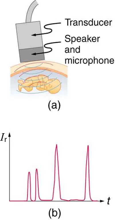
Figure 14.42 (a) An ultrasound speaker doubles as a microphone. Brief bleeps are broadcast, and echoes are recorded from various depths. (b) Graph of echo intensity versus time. The time for echoes to return is directly proportional to the distance of the reflector, yielding this information noninvasively. Image from OpenStax College Physics 2e, CC-BY 4.0
Image Description
The image consists of two parts labeled (a) and (b).
(a) This section shows a diagram of an ultrasound device used for examining a fetus. The device includes a transducer, speaker, and microphone positioned on a woman’s abdomen, with an image of a baby in the womb below it. Arrows point to the transducer and the speaker and microphone.
(b) This section displays a graph with an x-axis labeled “t” and a y-axis labeled “Ir“. The graph features multiple peaks, indicating varied intensity readings over time.
The most common ultrasound applications produce an image like that shown in Figure 14.43. The speaker-microphone broadcasts a directional beam, sweeping the beam across the area of interest. This is accomplished by having multiple ultrasound sources in the probe’s head, which are phased to interfere constructively in a given, adjustable direction. Echoes are measured as a function of position as well as depth. A computer constructs an image that reveals the shape and density of internal structures.
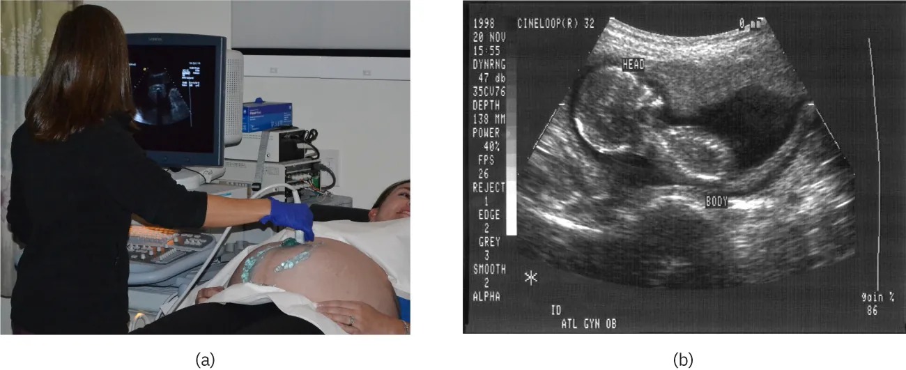
Figure 14.43 (a) An ultrasonic image is produced by sweeping the ultrasonic beam across the area of interest, in this case the person’s abdomen. Data are recorded and analyzed in a computer, providing a two-dimensional image (credit: COD Newsroom, Flickr). (b) Ultrasound image of 12-week-old fetus. Image from OpenStax College Physics 2e, CC-BY 4.0
How much detail can ultrasound reveal? The image in Figure 14.43 is typical of low-cost systems, but that in Figure 14.44 shows the remarkable detail possible with more advanced systems, including 3D imaging. Ultrasound today is commonly used in prenatal care. Such imaging can be used to see if the fetus is developing at a normal rate, and help in the determination of serious problems early in the pregnancy. Ultrasound is also in wide use to image the chambers of the heart and the flow of blood within the beating heart, using the Doppler effect (echocardiology).
Whenever a wave is used as a probe, it is very difficult to detect details smaller than its wavelength [latex]\lambda[/latex]. Indeed, current technology cannot do quite this well. Abdominal scans may use a 7-MHz frequency, and the speed of sound in tissue is about 1540 m/s—so the wavelength limit to detail would be [latex]\lambda = \frac{v_{w}}{f} = \frac{\text{1540 m}/\text{s}}{7 \times \text{10}^{6} \text{Hz}} = 0 . \text{22 mm}[/latex]. In practice, 1-mm detail is attainable, which is sufficient for many purposes. Higher-frequency ultrasound would allow greater detail, but it does not penetrate as well as lower frequencies do. The accepted rule of thumb is that you can effectively scan to a depth of about [latex]500 \lambda[/latex] into tissue. For 7 MHz, this penetration limit is [latex]500 \times 0.22 mm[/latex], which is 0.11 m. Higher frequencies may be employed in smaller organs, such as the eye, but are not practical for looking deep into the body.
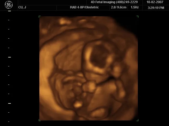
Figure 14.44 A 3D ultrasound image of a fetus. Image from OpenStax College Physics 2e, CC-BY 4.0
In addition to shape information, ultrasonic scans can produce density information superior to that found in X-rays, because the intensity of a reflected sound is related to changes in density. Sound is most strongly reflected at places where density changes are greatest.
Another major use of ultrasound in medical diagnostics is to detect motion and determine velocity through the Doppler shift of an echo, known as Doppler-shifted ultrasound. This technique is used to monitor fetal heartbeat, measure blood velocity, and detect occlusions in blood vessels, for example. (See Figure 14.45.) The magnitude of the Doppler shift in an echo is directly proportional to the velocity of whatever reflects the sound. Because an echo is involved, there is actually a double shift. The first occurs because the reflector (say a fetal heart) is a moving observer and receives a Doppler-shifted frequency. The reflector then acts as a moving source, producing a second Doppler shift.
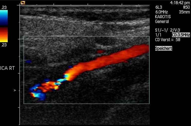
Figure 14.45 This Doppler-shifted ultrasonic image of a partially occluded artery uses color to indicate velocity. The highest velocities are in red, while the lowest are blue. The blood must move faster through the constriction to carry the same flow. Image from OpenStax College Physics 2e, CC-BY 4.0
A clever technique is used to measure the Doppler shift in an echo. The frequency of the echoed sound is superimposed on the broadcast frequency, producing beats. The beat frequency is [latex]F_{B} = \mid f_{1} - f_{2} \mid[/latex], and so it is directly proportional to the Doppler shift ([latex]f_{1} - f_{2}[/latex]) and hence, the reflector’s velocity. The advantage in this technique is that the Doppler shift is small (because the reflector’s velocity is small), so that great accuracy would be needed to measure the shift directly. But measuring the beat frequency is easy, and it is not affected if the broadcast frequency varies somewhat. Furthermore, the beat frequency is in the audible range and can be amplified for audio feedback to the medical observer.
Uses for Doppler-Shifted Radar
Doppler-shifted radar echoes are used to measure wind velocities in storms as well as aircraft and automobile speeds. The principle is the same as for Doppler-shifted ultrasound. There is evidence that bats and dolphins may also sense the velocity of an object (such as prey) reflecting their ultrasound signals by observing its Doppler shift.
Example 14.8
Calculate Velocity of Blood: Doppler-Shifted Ultrasound
Ultrasound that has a frequency of 2.50 MHz is sent toward blood in an artery that is moving toward the source at 20.0 cm/s, as illustrated in Figure 14.46. Use the speed of sound in human tissue as 1540 m/s. (Assume that the frequency of 2.50 MHz is accurate to seven significant figures.)
- What frequency does the blood receive?
- What frequency returns to the source?
- What beat frequency is produced if the source and returning frequencies are mixed?
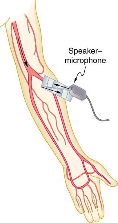
Figure 14.46 Ultrasound is partly reflected by blood cells and plasma back toward the speaker-microphone. Because the cells are moving, two Doppler shifts are produced—one for blood as a moving observer, and the other for the reflected sound coming from a moving source. The magnitude of the shift is directly proportional to blood velocity. Image from OpenStax College Physics 2e, CC-BY 4.0
Image Description
The image is a medical illustration showing an arm with a transparent section revealing the veins and arteries running through it. There is a device labeled “Speaker-microphone” attached to the arm, connected by a wire. The speaker-microphone appears to be placed over the major artery of the arm, possibly to detect blood flow or other vascular signals. The veins and arteries are shown in red, while the rest of the arm is depicted in a pale skin tone. The illustration highlights the use of a medical device on the arm for vascular monitoring.
Strategy
The first two questions can be answered using [latex]f_{\text{obs}} = f_{s} \left(\frac{v_{w}}{v_{w} \pm v_{s}}\right)[/latex] and [latex]f_{\text{obs}} = f_{s} \left(\frac{v_{w} \pm v_{\text{obs}}}{v_{w}}\right)[/latex] for the Doppler shift. The last question asks for beat frequency, which is the difference between the original and returning frequencies.
Solution for (a)
(1) Identify knowns:
- The blood is a moving observer, and so the frequency it receives is given by
[latex]f_{\text{obs}} = f_{s} \left(\frac{v_{w} \pm v_{\text{obs}}}{v_{w}}\right) .[/latex]
14.43 - [latex]v_{b}[/latex] is the blood velocity ([latex]v_{\text{obs}}[/latex] here) and the plus sign is chosen because the motion is toward the source.
(2) Enter the given values into the equation.
[latex]f_{\text{obs}} = \left(2, \text{500} , \text{000 Hz}\right) \left(\frac{\text{1540 m}/\text{s} + 0 . \text{2 m}/\text{s}}{\text{1540 m}/\text{s}}\right)[/latex]
(3) Calculate to find the frequency: 2,500,325 Hz.
Solution for (b)
(1) Identify knowns:
- The blood acts as a moving source.
- The microphone acts as a stationary observer.
- The frequency leaving the blood is 2,500,325 Hz, but it is shifted upward as given by
[latex]f_{\text{obs}} = f_{s} \left(\frac{v_{w}}{v_{w} – v_{b}}\right) .[/latex]
14.45[latex]f_{obs}[/latex] is the frequency received by the speaker-microphone.
- The source velocity is [latex]v_{b}[/latex].
- The minus sign is used because the motion is toward the observer.
The minus sign is used because the motion is toward the observer.
(2) Enter the given values into the equation:
[latex]f_{\text{obs}} = \left(2, \text{500} , \text{325 Hz}\right) \left(\frac{\text{1540 m}/\text{s}}{\text{1540 m}/\text{s } - 0 . \text{200 m}/\text{s}}\right)[/latex]
(3) Calculate to find the frequency returning to the source: 2,500,649 Hz.
Solution for (c)
(1) Identify knowns:
- The beat frequency is simply the absolute value of the difference between [latex]f_{s}[/latex] and [latex]f_{\text{obs}}[/latex], as stated in:
[latex]f_{B} = \mid f_{\text{obs}} - f_{s} \mid .[/latex]
14.47
(2) Substitute known values:
[latex]\mid 2, \text{500} , \text{649} \text{Hz} - 2, \text{500} , \text{000} \text{Hz} \mid[/latex]
(3) Calculate to find the beat frequency: 649 Hz.
Discussion
The Doppler shifts are quite small compared with the original frequency of 2.50 MHz. It is far easier to measure the beat frequency than it is to measure the echo frequency with an accuracy great enough to see shifts of a few hundred hertz out of a couple of megahertz. Furthermore, variations in the source frequency do not greatly affect the beat frequency, because both [latex]f_{s}[/latex] and [latex]f_{\text{obs}}[/latex]would increase or decrease. Those changes subtract out in [latex]f_{B} = \mid f_{\text{obs}} - f_{s} \mid .[/latex]
Industrial and Other Applications of Ultrasound
Industrial, retail, and research applications of ultrasound are common. A few are discussed here. Ultrasonic cleaners have many uses. Jewelry, machined parts, and other objects that have odd shapes and crevices are immersed in a cleaning fluid that is agitated with ultrasound typically about 40 kHz in frequency. The intensity is great enough to cause cavitation, which is responsible for most of the cleansing action. Because cavitation-produced shock pressures are large and well transmitted in a fluid, they reach into small crevices where even a low-surface-tension cleaning fluid might not penetrate.
Sonar is a familiar application of ultrasound. Sonar typically employs ultrasonic frequencies in the range from 30.0 to 100 kHz. Bats, dolphins, submarines, and even some birds use ultrasonic sonar. Echoes are analyzed to give distance and size information both for guidance and finding prey. In most sonar applications, the sound reflects quite well because the objects of interest have significantly different density than the medium in which they travel. When the Doppler shift is observed, velocity information can also be obtained. Submarine sonar can be used to obtain such information, and there is evidence that some bats also sense velocity from their echoes.
Similarly, there are a range of relatively inexpensive devices that measure distance by timing ultrasonic echoes. Many cameras, for example, use such information to focus automatically. Some doors open when their ultrasonic ranging devices detect a nearby object, and certain home security lights turn on when their ultrasonic rangers observe motion. Ultrasonic “measuring tapes” also exist to measure such things as room dimensions. Sinks in public restrooms are sometimes automated with ultrasound devices to turn faucets on and off when people wash their hands. These devices reduce the spread of germs and can conserve water.
Ultrasound is used for nondestructive testing in industry and by the military. Because ultrasound reflects well from any large change in density, it can reveal cracks and voids in solids, such as aircraft wings, that are too small to be seen with x-rays. For similar reasons, ultrasound is also good for measuring the thickness of coatings, particularly where there are several layers involved.
Basic research in solid state physics employs ultrasound. Its attenuation is related to a number of physical characteristics, making it a useful probe. Among these characteristics are structural changes such as those found in liquid crystals, the transition of a material to a superconducting phase, as well as density and other properties.
These examples of the uses of ultrasound are meant to whet the appetites of the curious, as well as to illustrate the underlying physics of ultrasound. There are many more applications, as you can easily discover for yourself.
Check Your Understanding
Why is it possible to use ultrasound both to observe a fetus in the womb and also to destroy cancerous tumors in the body?
Click for Solution
Solution
Ultrasound can be used medically at different intensities. Lower intensities do not cause damage and are used for medical imaging. Higher intensities can pulverize and destroy targeted substances in the body, such as tumors.
