4.4 Newton’s Third Law of Motion: Symmetry in Forces
Learning Objectives
By the end of this section, you will be able to:
- Understand Newton’s third law of motion.
- Apply Newton’s third law to define systems and solve problems of motion.
Baseball relief pitcher Mariano Rivera was so highly regarded that during his retirement year, opposing teams conducted farewell presentations when he played at their stadiums. The Minnesota Twins offered a unique gift: A chair made of broken bats. Any pitch can break a bat, but with Rivera’s signature pitch—known as a cutter—the ball and the bat frequently came together at a point that shattered the hardwood. Typically, we think of a baseball or softball hitter exerting a force on the incoming ball, and baseball analysts focus on the resulting “exit velocity” as a key statistic. But the force of the ball can do its own damage. This is exactly what happens whenever one body exerts a force on another—the first also experiences a force (equal in magnitude and opposite in direction). Numerous common experiences, such as stubbing a toe or pushing off the floor during a jump, confirm this. It is precisely stated in Newton’s third law of motion.
Newton’s Third Law of Motion
Whenever one body exerts a force on a second body, the first body experiences a force that is equal in magnitude and opposite in direction to the force that it exerts.
This law represents a certain symmetry in nature: Forces always occur in pairs, and one body cannot exert a force on another without experiencing a force itself. We sometimes refer to this law loosely as “action-reaction,” where the force exerted is the action and the force experienced as a consequence is the reaction. Newton’s third law has practical uses in analyzing the origin of forces and understanding which forces are external to a system.
We can readily see Newton’s third law at work by taking a look at how people move about. Consider a swimmer pushing off from the side of a pool, as illustrated in Figure 4.9. She pushes against the pool wall with her feet and accelerates in the direction opposite to that of her push. The wall has exerted an equal and opposite force back on the swimmer. You might think that two equal and opposite forces would cancel, but they do not because they act on different systems. In this case, there are two systems that we could investigate: the swimmer or the wall. If we select the swimmer to be the system of interest, as in the figure, then [latex]\textbf{F}_{\text{wall on feet}}[/latex] is an external force on this system and affects its motion. The swimmer moves in the direction of [latex]\textbf{F}_{\text{wall on feet}}[/latex]. In contrast, the force [latex]\textbf{F}_{\text{feet on wall}}[/latex] acts on the wall and not on our system of interest. Thus [latex]\textbf{F}_{\text{feet on wall}}[/latex] does not directly affect the motion of the system and does not cancel [latex]\textbf{F}_{\text{wall on feet}}[/latex]. Note that the swimmer pushes in the direction opposite to that in which she wishes to move. The reaction to her push is thus in the desired direction.
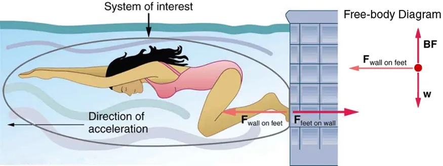
Figure 4.9 When the swimmer exerts a force [latex]\textbf{F}_{\text{feet on wall}}[/latex] on the wall, she accelerates in the direction opposite to that of her push. This means the net external force on her is in the direction opposite to [latex]\textbf{F}_{\text{feet on wall}}[/latex]. This opposition occurs because, in accordance with Newton’s third law of motion, the wall exerts a force [latex]\textbf{F}_{\text{wall on feet}}[/latex] on her, equal in magnitude but in the direction opposite to the one she exerts on it. The line around the swimmer indicates the system of interest. Note that [latex]\textbf{F}_{\text{feet on wall}}[/latex] does not act on this system (the swimmer) and, thus, does not cancel [latex]\textbf{F}_{\text{wall on feet}}[/latex]. Thus the free-body diagram shows only [latex]\textbf{F}_{\text{wall on feet}}[/latex], [latex]\textbf{w}[/latex], the gravitational force, and [latex]\textbf{BF}[/latex], the buoyant force of the water supporting the swimmer’s weight. The vertical forces [latex]\textbf{w}[/latex] and [latex]\textbf{BF}[/latex] cancel since there is no vertical motion. Image from OpenStax College Physics 2e, CC-BY 4.0
Image Description
The image depicts a swimmer in a pool, positioned horizontally and pushing against the wall with her feet. She is wearing a pink swimsuit and has her arms extended forward. The area around her is labeled “System of interest,” with an oval shape surrounding her body.
An arrow labeled “Direction of acceleration” points from right to left, indicating the swimmer’s intended movement direction.
To the right, a “Free-body Diagram” is shown, illustrating the forces acting on the swimmer. The diagram includes:
– An arrow labeled “Fwall on feet” pointing left, representing the force exerted by the wall on the swimmer’s feet.
– An arrow labeled “Ffeet on wall” pointing right, indicating the force exerted by the swimmer’s feet on the wall.
– An arrow labeled “BF” pointing upwards.
– An arrow labeled “w” pointing downwards, representing the weight force.
The wall is depicted with a tiled pattern, and the swimmer’s body is streamlined, emphasizing movement.
Other examples of Newton’s third law are easy to find. As a professor walks in front of a whiteboard, she exerts a force backward on the floor. The floor exerts a reaction force forward on the professor that causes her to accelerate forward. Similarly, a car accelerates because the ground pushes forward on the drive wheels in reaction to the drive wheels pushing backward on the ground. You can see evidence of the wheels pushing backward when tires spin on a gravel road and throw rocks backward. In another example, rockets move forward by expelling gas backward at high velocity. This means the rocket exerts a large backward force on the gas in the rocket combustion chamber, and the gas therefore exerts a large reaction force forward on the rocket. This reaction force is called thrust. It is a common misconception that rockets propel themselves by pushing on the ground or on the air behind them. They actually work better in a vacuum, where they can more readily expel the exhaust gases. Helicopters similarly create lift by pushing air down, thereby experiencing an upward reaction force. Birds and airplanes also fly by exerting force on air in a direction opposite to that of whatever force they need. For example, the wings of a bird force air downward and backward in order to get lift and move forward. An octopus propels itself in the water by ejecting water through a funnel from its body, similar to a jet ski. Boxers and other martial arts fighters experience reaction forces when they punch, sometimes breaking their hand by hitting an opponent’s body.
Example 4.3
Getting Up To Speed: Choosing the Correct System
A physics professor pushes a cart of demonstration equipment to a lecture hall, as seen in Figure 4.10. Her mass is 65.0 kg, the cart’s is 12.0 kg, and the equipment’s is 7.0 kg. Calculate the acceleration produced when the professor exerts a backward force of 150 N on the floor. All forces opposing the motion, such as friction on the cart’s wheels and air resistance, total 24.0 N.
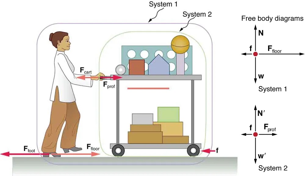
Figure 4.10 A professor pushes a cart of demonstration equipment. The lengths of the arrows are proportional to the magnitudes of the forces (except for [latex]\textbf{f}[/latex], since it is too small to draw to scale). Different questions are asked in each example; thus, the system of interest must be defined differently for each. System 1 is appropriate for this example, since it asks for the acceleration of the entire group of objects. Only [latex]\textbf{F}_{\text{floor}}[/latex] and [latex]\textbf{f}[/latex] are external forces acting on System 1 along the line of motion. All other forces either cancel or act on the outside world. System 2 is chosen for so that [latex]\textbf{F}_{\text{prof}}[/latex] will be an external force and enter into Newton’s second law. Note that the free-body diagrams, which allow us to apply Newton’s second law, vary with the system chosen. Image from OpenStax College Physics 2e, CC-BY 4.0
Image Description
This image illustrates a physics concept involving forces and free-body diagrams. It shows a person pushing a cart. Various forces are labeled with arrows to explain the dynamics:
– The person is pushing the cart with a force labeled as “Fcart“.
– The cart is loaded with boxes and shapes, illustrating a system labeled “System 1”.
– The cart’s wheels are shown with a smaller circle, and the force of friction is labeled as “f”.
– The floor exerts a force labeled “Ffloor” against the cart in the opposite direction of “Fcart“.
– A force labeled “Ffoot” is acting on the person’s foot in the left direction.
– Another system, “System 2”, is labeled around the cart.
– Two free-body diagrams are shown on the right side:
– System 1 diagram shows forces “N” (normal force), “w” (weight), “f” (friction), and “Ffloor” (floor force).
– System 2 diagram shows forces “N'” (normal force), “w'” (weight), “f” (friction), and “Fprof” (professor’s force).
The person is shown with a neutral expression, wearing a white top and brown pants, and is actively engaging in pushing the cart forward.
Strategy
Since they accelerate as a unit, we define the system to be the professor, cart, and equipment. This is System 1 in Figure 4.10. The professor pushes backward with a force [latex]\textbf{F}_{\text{foot}}[/latex] of 150 N. According to Newton’s third law, the floor exerts a forward reaction force [latex]\textbf{F}_{\text{floor}}[/latex] of 150 N on System 1. Because all motion is horizontal, we can assume there is no net force in the vertical direction. The problem is therefore one-dimensional along the horizontal direction. As noted, [latex]\textbf{f}[/latex] opposes the motion and is thus in the opposite direction of [latex]\textbf{F}_{\text{floor}}[/latex]. Note that we do not include the forces [latex]\textbf{F}_{\text{prof}}[/latex] or [latex]\textbf{F}_{\text{cart}}[/latex] because these are internal forces, and we do not include [latex]\textbf{F}_{\text{foot}}[/latex] because it acts on the floor, not on the system. There are no other significant forces acting on System 1. If the net external force can be found from all this information, we can use Newton’s second law to find the acceleration as requested. See the free-body diagram in the figure.
Solution
Newton’s second law is given by
[latex]a = \frac{F_{\text{net}}}{m} .[/latex]
The net external force on System 1 is deduced from Figure 4.10 and the discussion above to be
[latex]F_{\text{net}} = F_{\text{floor}} - f = \text{150 N} - \text{24} . \text{0 N} = \text{126 N} .[/latex]
The mass of System 1 is
[latex]m = \left(\right. \text{65} . \text{0 } + \text{ 12} . \text{0 } + \text{ 7} . 0 \left.\right) \text{ kg } = \text{ 84 kg} .[/latex]
These values of [latex]F_{\text{net}}[/latex] and [latex]m[/latex] produce an acceleration of
[latex]a = \frac{F_{\text{net}}}{m} , \\ a = \frac{1 \text{26 N}}{\text{84 kg}} = \text{ 1} . \text{5 m}/\text{s}^{2} .[/latex]
Discussion
None of the forces between components of System 1, such as between the professor’s hands and the cart, contribute to the net external force because they are internal to System 1. Another way to look at this is to note that forces between components of a system cancel because they are equal in magnitude and opposite in direction. For example, the force exerted by the professor on the cart results in an equal and opposite force back on her. In this case both forces act on the same system and, therefore, cancel. Thus internal forces (between components of a system) cancel. Choosing System 1 was crucial to solving this problem.
Example 4.4
Force on the Cart—Choosing a New System
Calculate the force the professor exerts on the cart in Figure 4.10 using data from the previous example if needed.
Strategy
If we now define the system of interest to be the cart plus equipment (System 2 in Figure 4.10), then the net external force on System 2 is the force the professor exerts on the cart minus friction. The force she exerts on the cart, [latex]\textbf{F}_{\text{prof}}[/latex], is an external force acting on System 2. [latex]\textbf{F}_{\text{prof}}[/latex] was internal to System 1, but it is external to System 2 and will enter Newton’s second law for System 2.
Solution
Newton’s second law can be used to find [latex]\textbf{F}_{\text{prof}}[/latex]. Starting with
[latex]a = \frac{F_{\text{net}}}{m}[/latex]
and noting that the magnitude of the net external force on System 2 is
[latex]F_{\text{net}} = F_{\text{prof}} - f ,[/latex]
we solve for [latex]F_{\text{prof}}[/latex], the desired quantity:
[latex]F_{\text{prof}} = F_{\text{net}} + f .[/latex]
The value of [latex]f[/latex] is given, so we must calculate net [latex]F_{\text{net}}[/latex]. That can be done since both the acceleration and mass of System 2 are known. Using Newton’s second law we see that
[latex]F_{\text{net}} = \text{ma} ,[/latex]
where the mass of System 2 is 19.0 kg ([latex]m[/latex]= 12.0 kg + 7.0 kg) and its acceleration was found to be [latex]a = 1.5 \text{ m}/\text{s}^{2}[/latex] in the previous example. Thus,
[latex]F_{\text{net}} = \text{ma} ,[/latex]
[latex]F_{\text{net}} = \left(\right. \text{19} . \text{0 kg} \left.\right) \left(\right. 1.5 \text{ m}/\text{s}^{2} \left.\right) = \text{29 N} .[/latex]
Now we can find the desired force:
[latex]F_{\text{prof}} = F_{\text{net}} + f ,[/latex]
[latex]F_{\text{prof}} = \text{29 N} + \text{24}.\text{0 N} = \text{53 N} .[/latex]
Discussion
It is interesting that this force is significantly less than the 150-N force the professor exerted backward on the floor. Not all of that 150-N force is transmitted to the cart; some of it accelerates the professor.
The choice of a system is an important analytical step both in solving problems and in thoroughly understanding the physics of the situation (which is not necessarily the same thing).
PhET Explorations
Gravity Force Lab
Visualize the gravitational force that two objects exert on each other. Change properties of the objects in order to see how it changes the gravity force.
