4.1 Development of Force Concept
Learning Objectives
By the end of this section, you will be able to:
- Understand the definition of force.
Dynamics is the study of the forces that cause objects and systems to move. To understand this, we need a working definition of force. Our intuitive definition of force—that is, a push or a pull—is a good place to start. We know that a push or pull has both magnitude and direction (therefore, it is a vector quantity) and can vary considerably in each regard. For example, a cannon exerts a strong force on a cannonball that is launched into the air. In contrast, Earth exerts only a tiny downward pull on a flea. Our everyday experiences also give us a good idea of how multiple forces add. If two people push in different directions on a third person, as illustrated in Figure 4.3, we might expect the total force to be in the direction shown. Since force is a vector, it adds just like other vectors, as illustrated in Figure 4.3(a) for two ice skaters. Forces, like other vectors, are represented by arrows and can be added using the familiar head-to-tail method or by trigonometric methods. These ideas were developed in Two-Dimensional Kinematics.
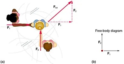
Figure 4.3 Part (a) shows an overhead view of two ice skaters pushing on a third. Forces are vectors and add like other vectors, so the total force on the third skater is in the direction shown. In part (b), we see a free-body diagram representing the forces acting on the third skater. Image from OpenStax College Physics 2e, CC-BY 4.0
Image Description
The image consists of two parts labeled (a) and (b).
(a) This section shows a diagram of three people interacting with forces involved. The people are positioned in a top-down view. The diagram includes force vectors:
– F1: A horizontal force vector pointing left, applied by the person on the left.
– F2: A vertical force vector pointing upward, applied by the person at the bottom.
– F_tot: The resultant force vector depicted as a diagonal line in the upward-right direction, formed by combining F1 and F2.
The vectors are represented with arrows, indicating both direction and magnitude.
(b) This section displays a simplified free-body diagram:
– The diagram includes a dot representing an object.
– A horizontal arrow labeled F1 points to the right, indicating a horizontal force.
– A vertical arrow labeled F2 points upward, indicating a vertical force.
– Labels indicate the axes and respective forces.
Overall, the image illustrates the concept of vector addition and free-body diagrams in physics through a top-down view of people applying forces and a corresponding simplified diagram.
Figure 4.3(b) is our first example of a free-body diagram, which is a technique used to illustrate all the external forces acting on a body. The body is represented by a single isolated point (or free body), and only those forces acting on the body from the outside (external forces) are shown. (These forces are the only ones shown, because only external forces acting on the body affect its motion. We can ignore any internal forces within the body.) Free-body diagrams are very useful in analyzing forces acting on a system and are employed extensively in the study and application of Newton’s laws of motion.
A more quantitative definition of force can be based on some standard force, just as distance is measured in units relative to a standard distance. One possibility is to stretch a spring a certain fixed distance, as illustrated in Figure 4.4, and use the force it exerts to pull itself back to its relaxed shape—called a restoring force—as a standard. The magnitude of all other forces can be stated as multiples of this standard unit of force. Many other possibilities exist for standard forces. (One that we will encounter in Magnetism is the magnetic force between two wires carrying electric current.) Some alternative definitions of force will be given later in this chapter.
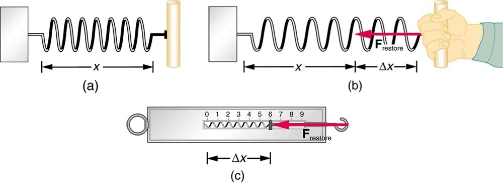
Figure 4.4 The force exerted by a stretched spring can be used as a standard unit of force. (a) This spring has a length [latex]x[/latex] when undistorted. (b) When stretched a distance [latex]Δ x[/latex], the spring exerts a restoring force, [latex]\textbf{F}_{\text{restore}}[/latex], which is reproducible. (c) A spring scale is one device that uses a spring to measure force. The force [latex]\textbf{F}_{\text{restore}}[/latex] is exerted on whatever is attached to the hook. Here [latex]\textbf{F}_{\text{restore}}[/latex] has a magnitude of 6 units in the force standard being employed. Image from OpenStax College Physics 2e, CC-BY 4.0
Image Description
The image consists of three diagrams demonstrating the concept of spring force and Hooke’s Law.
1. Diagram (a):
– Shows a spring in its natural, uncompressed state.
– The spring is attached between two blocks.
– A distance labeled as “x” is indicated, measuring from the left block to the right block.
– There’s no external force applied.
2. Diagram (b):
– Illustrates the spring in a stretched state.
– A hand is pulling on the right end of the spring, extending it.
– The extension is denoted as “Δx” from the original position “x.”
– A red arrow labeled “F restore” indicates the restoring force of the spring, pointing leftward, opposing the extension.
3. Diagram (c):
– Depicts a spring scale.
– The scale’s face is marked from 0 to 9.
– Inside the scale, a spring is shown stretched, with “Δx” indicating the extension from its unstretched position.
– A red arrow labeled “F restore” points leftwards within the scale, signifying the spring’s restoring force.
These diagrams collectively illustrate how a spring exerts a restoring force when stretched, with this force being proportional to the extension of the spring, as per Hooke’s Law.
Take-Home Experiment: Force Standards
To investigate force standards and cause and effect, get two identical rubber bands. Hang one rubber band vertically on a hook. Find a small household item that could be attached to the rubber band using a paper clip, and use this item as a weight to investigate the stretch of the rubber band. Measure the amount of stretch produced in the rubber band with one, two, and four of these (identical) items suspended from the rubber band. What is the relationship between the number of items and the amount of stretch? How large a stretch would you expect for the same number of items suspended from two rubber bands? What happens to the amount of stretch of the rubber band (with the weights attached) if the weights are also pushed to the side with a pencil?
