3.4 Projectile Motion
Learning Objectives
By the end of this section, you will be able to:
- Identify and explain the properties of a projectile, such as acceleration due to gravity, range, maximum height, and trajectory.
- Determine the location and velocity of a projectile at different points in its trajectory.
- Apply the principle of independence of motion to solve projectile motion problems.
Projectile motion is the motion of an object thrown or projected into the air, subject to only the acceleration of gravity. The object is called a projectile, and its path is called its trajectory. The motion of falling objects, as covered in 2.6 Problem-Solving Basics for One-Dimensional Kinematics, is a simple one-dimensional type of projectile motion in which there is no horizontal movement. In this section, we consider two-dimensional projectile motion, such as that of a football or other object for which air resistance is negligible.
The most important fact to remember here is that motions along perpendicular axes are independent and thus can be analyzed separately. This fact was discussed in 3.1 Kinematics in Two Dimensions: An Introduction, where vertical and horizontal motions were seen to be independent. The key to analyzing two-dimensional projectile motion is to break it into two motions, one along the horizontal axis and the other along the vertical. (This choice of axes is the most sensible, because acceleration due to gravity is vertical—thus, there will be no acceleration along the horizontal axis when air resistance is negligible.) As is customary, we call the horizontal axis the x-axis and the vertical axis the y-axis. Figure 3.34 illustrates the notation for displacement, where [latex]\mathbf{s}[/latex] is defined to be the total displacement and [latex]\mathbf{x}[/latex] and [latex]\mathbf{y}[/latex] are its components along the horizontal and vertical axes, respectively. The magnitudes of these vectors are s, x, and y. (Note that in the last section we used the notation [latex]\mathbf{A}[/latex] to represent a vector with components [latex]\mathbf{A}_{x}[/latex] and [latex]\mathbf{A}_{y}[/latex]. If we continued this format, we would call displacement [latex]\mathbf{s}[/latex] with components [latex]\mathbf{s}_{x}[/latex] and [latex]\mathbf{s}_{y}[/latex]. However, to simplify the notation, we will simply represent the component vectors as [latex]\mathbf{x}[/latex] and [latex]\mathbf{y}[/latex].)
Of course, to describe motion we must deal with velocity and acceleration, as well as with displacement. We must find their components along the x– and y-axes, too. We will assume all forces except gravity (such as air resistance and friction, for example) are negligible. The components of acceleration are then very simple:
[latex]a_{y} = – g = – 9.80 m /\text{s}^{2}[/latex]. (Note that this definition assumes that the upwards direction is defined as the positive direction. If you arrange the coordinate system instead such that the downwards direction is positive, then acceleration due to gravity takes a positive value.) Because gravity is vertical,
[latex]a_{x} = 0[/latex]. Both accelerations are constant, so the kinematic equations can be used.
Review of Kinematic Equations (constant [latex]{\color{white}a}[/latex])
[latex]x = x_{0} + \overset{-}{v} t[/latex]
[latex]\overset{-}{v} = \frac{v_{0} + v}{2}[/latex]
[latex]v = v_{0} + \text{at}[/latex]
[latex]x = x_{0} + v_{0} t + \frac{1}{2} \text{at}^{2}[/latex]
[latex]v^{2} = v_{0}^{2} + 2 a \left(\right. x - x_{0} \left.\right) .[/latex]
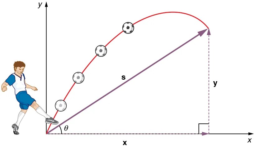
Figure 3.34 The total displacement [latex]\mathbf{s}[/latex] of a soccer ball at a point along its path. The vector [latex]\mathbf{s}[/latex] has components [latex]\mathbf{x}[/latex] and [latex]\mathbf{y}[/latex] along the horizontal and vertical axes. Its magnitude is [latex]s[/latex], and it makes an angle [latex]\theta[/latex] with the horizontal. Image from OpenStax College Physics 2e, CC-BY 4.0
Image Description
The image depicts a diagram illustrating the parabolic trajectory of a soccer ball being kicked. A soccer player dressed in a blue and white uniform is shown on the left, kicking the ball. The ball follows a curved, red path, moving upward then downward, with several positions of the ball marked along the trajectory to show its motion through the air.
There are two axes in the diagram:
- The vertical axis is labeled y and indicates the height of the ball.
- The horizontal axis is labeled x and represents the distance traveled by the ball.
An angle, θ, is shown at the point where the player kicks the ball, highlighting the initial angle of the ball’s trajectory relative to the horizontal axis. A straight, purple line labeled s indicates the distance of the projectile’s path from the kicking point to the apex of its path. At the endpoint of the path, a dashed line connects from the ball to both the horizontal and vertical axes, illustrating the maximum height (y) and horizontal distance (x) the ball achieves.
Given these assumptions, the following steps are then used to analyze projectile motion:
Step 1. Resolve or break the motion into horizontal and vertical components along the x- and y-axes. These axes are perpendicular, so
[latex]A_{x} = A \text{cos} \theta[/latex] and
[latex]A_{y} = A \text{sin} \theta[/latex] are used. The magnitude of the components of displacement
[latex]\mathbf{s}[/latex] along these axes are [latex]x[/latex] and
[latex]y.[/latex] The magnitudes of the components of the velocity [latex]\mathbf{v}[/latex] are
[latex]v_{x} = v \text{cos} \theta[/latex] and
[latex]v_{y} = v \text{sin} θ,[/latex] where
[latex]v[/latex] is the magnitude of the velocity and [latex]\theta[/latex] is its direction, as shown in Figure 3.35. Initial values are denoted with a subscript 0, as usual.
Step 2. Treat the motion as two independent one-dimensional motions, one horizontal and the other vertical. The kinematic equations for horizontal and vertical motion take the following forms:
[latex]\text{Horizontal Motion} \left(\right. a_{x} = 0 \left.\right)[/latex]
[latex]x = x_{0} + v_{x} t[/latex]
[latex]v_{x} = v_{0 x} = v_{x} = \text{velocity is a constant}.[/latex]
[latex]\begin{align*}\text{Vertical Motion} \left(\right. \text{if positive is up} \\ a_{y} = - g = - 9. \text{80} \text{m}/\text{s}^{2} \left.\right)\end{align*}[/latex]
[latex]y = y_{0} + \frac{1}{2} \left(\right. v_{0 y} + v_{y} \left.\right) t[/latex]
[latex]v_{y} = v_{0 y} - \text{gt}[/latex]
[latex]y = y_{0} + v_{0 y} t - \frac{1}{2} gt^{2}[/latex]
[latex]v_{y}^{2} = v_{0 y}^{2} - 2 g \left(\right. y - y_{0} \left.\right) .[/latex]
Step 3. Solve for the unknowns in the two separate motions—one horizontal and one vertical. Note that the only common variable between the motions is time [latex]t[/latex]. The problem solving procedures here are the same as for one-dimensional kinematics and are illustrated in the solved examples below.
Step 4. Recombine the two motions to find the total displacement [latex]\textbf{s}[/latex] and velocity [latex]\textbf{v}[/latex]. Because the x – and y -motions are perpendicular, we determine these vectors by using the techniques outlined in the 3.3 Vector Addition and Subtraction: Analytical Methods and employing [latex]A = \sqrt{A_{x}^{2} + A_{y}^{2}}[/latex] and [latex]\theta = \text{tan}^{- 1} \left(\right. A_{y} / A_{x} \left.\right)[/latex] in the following form, where [latex]\theta[/latex] is the direction of the displacement [latex]\mathbf{s}[/latex] and [latex]\theta_{v}[/latex] is the direction of the velocity [latex]\mathbf{v}[/latex]:
Total displacement and velocity
[latex]s = \sqrt{x^{2} + y^{2}}[/latex]
[latex]\theta = \text{tan}^{- 1} \left(\right. y / x \left.\right)[/latex]
[latex]v = \sqrt{v_{x}^{2} + v_{y}^{2}}[/latex]
[latex]\theta_{v} = \text{tan}^{- 1} \left(\right. v_{y} / v_{x} \left.\right) .[/latex]
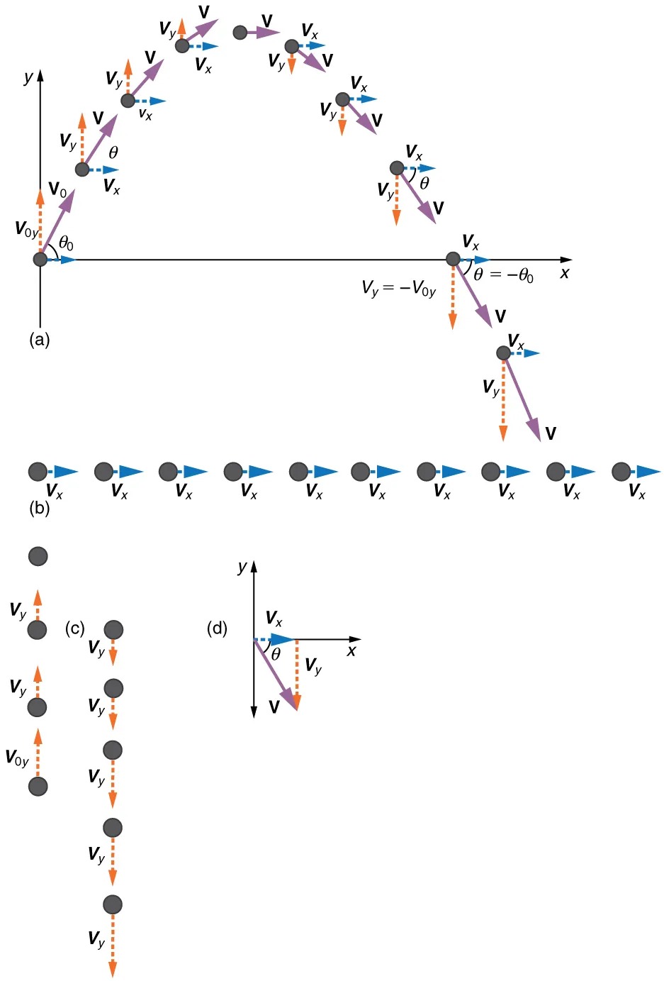
Figure 3.35 (a) We analyze two-dimensional projectile motion by breaking it into two independent one-dimensional motions along the vertical and horizontal axes. (b) The horizontal motion is simple, because [latex]a_{x} = 0[/latex] and [latex]v_{x}[/latex] is thus constant. (c) The velocity in the vertical direction begins to decrease as the object rises; at its highest point, the vertical velocity is zero. As the object falls towards the Earth again, the vertical velocity increases again in magnitude but points in the opposite direction to the initial vertical velocity. (d) The x – and y -motions are recombined to give the total velocity at any given point on the trajectory. Image from OpenStax College Physics 2e, CC-BY 4.0
Image Description
The image consists of four labeled diagrams (a, b, c, and d) illustrating the components of motion:
1. Diagram (a):
– Shows a projectile motion trajectory in a parabolic path.
– The projectile starts at an origin point on the x-y axis, launching at angle \( \theta_0 \) with initial velocity \( v_0 \).
– Horizontal velocity \( v_x \) is constant (depicted by blue arrows), while vertical velocity \( v_y \) (orange arrows) changes direction and magnitude along the trajectory.
– The resulting velocity \( v \) is shown as purple arrows, with varying direction and magnitude.
– The angle of velocity \( \theta \) changes from launch to landing.
2. Diagram (b):
– Displays several identical projectiles moving horizontally.
– All projectiles have a constant horizontal velocity \( v_x \) indicated by blue arrows, showing no vertical component of motion.
3. Diagram (c):
– Illustrates projectiles moving vertically, affected by gravity.
– Projectiles are shown ascending and descending, with initial vertical velocity \( v_{0y} \) at ascent and just \( v_y \) at other points.
4. Diagram (d):
– A detailed breakdown of velocity components.
– Angle \( \theta \) is measured between the horizontal axis and velocity vector \( v \).
– Velocity is split into horizontal \( v_x \) (blue arrow) and vertical \( v_y \) (orange arrow) components.
– All vectors originate from a common point on the x-y axis.
Each diagram provides a different perspective on velocity components in projectile motion, highlighting the effects of gravity and trajectory changes.
Example 3.4
A Fireworks Projectile Explodes High and Away
During a fireworks display, a shell is shot into the air with an initial speed of 70.0 m/s at an angle of [latex]75.0º[/latex] above the horizontal, as illustrated in Figure 3.36. The fuse is timed to ignite the shell just as it reaches its highest point above the ground. (a) Calculate the height at which the shell explodes. (b) How much time passed between the launch of the shell and the explosion? (c) What is the horizontal displacement of the shell when it explodes?
Strategy
Because air resistance is negligible for the unexploded shell, the analysis method outlined above can be used. The motion can be broken into horizontal and vertical motions in which [latex]a_{x} = 0[/latex] and [latex]a_{y} = – g[/latex]. We can then define [latex]x_{0}[/latex] and [latex]y_{0}[/latex] to be zero and solve for the desired quantities.
Solution for (a)
By “height” we mean the altitude or vertical position [latex]y[/latex] above the starting point. The highest point in any trajectory, called the apex, is reached when [latex]v_{y} = 0[/latex]. Since we know the initial and final velocities as well as the initial position, we use the following equation to find [latex]y[/latex]:
[latex]v_{y}^{2} = v_{0 y}^{2} - 2 g \left(\right. y - y_{0} \left.\right) .[/latex]
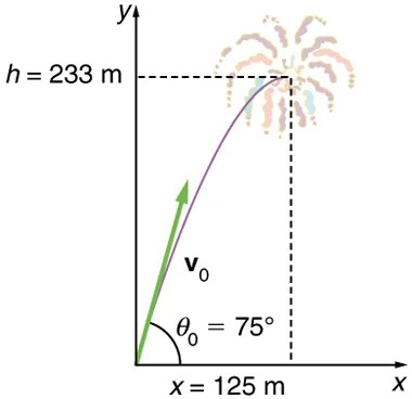
Figure 3.36 The trajectory of a fireworks shell. The fuse is set to explode the shell at the highest point in its trajectory, which is found to be at a height of 233 m and 125 m away horizontally. Image from OpenStax College Physics 2e, CC-BY 4.0
Image Description
The image depicts a trajectory of a firework projectile launched at an angle. Here is a detailed description:
– The x-y coordinate system is shown, with x representing the horizontal axis and y representing the vertical axis.
– The initial launch angle, labeled as θ₀ = 75°, is marked with an arrow starting from the origin (0,0) and pointing upwards.
– The initial velocity is labeled as v₀ alongside the green arrow indicating the projectile’s launch direction.
– A curved trajectory path is drawn from the origin, peaking at the coordinates where a firework explodes.
– The firework explosion is visually represented at the upper right side of the graph with colorful bursts.
– The horizontal distance from the origin to the explosion point is labeled as x = 125 m.
– The vertical height from the origin to the explosion point is labeled as h = 233 m.
– Dashed lines from both the horizontal and vertical axes intersect at the explosion point, indicating the maximum height and distance reached by the firework.
Because [latex]y_{0}[/latex] and [latex]v_{y}[/latex] are both zero, the equation simplifies to
[latex]0 = v_{0 y}^{2} - 2 \text{gy}.[/latex]
Solving for [latex]y[/latex] gives
[latex]y = \frac{v_{0 y}^{2}}{2 g} .[/latex]
Now we must find
[latex]v_{0 y}[/latex], the component of the initial velocity in the y-direction. It is given by
[latex]v_{0 y} = v_{0} \text{sin} \theta[/latex], where
[latex]v_{0 y}[/latex] is the initial velocity of 70.0 m/s, and
[latex]\theta_{0} = 75.0º[/latex] is the initial angle. Thus,
[latex]v_{0 y} = v_{0} \text{sin} \theta_{0} = \left(\right. \text{70}.\text{0 m}/\text{s} \left.\right) \left(\right. \text{sin 75}º \left.\right) = \text{67}.\text{6 m}/\text{s}.[/latex]
and [latex]y[/latex] is
[latex]y = \frac{\left(\right. \text{67} .\text{6 m}/\text{s} \left.\right)^{2}}{2 \left(\right. 9 . \text{80 m} /\text{s}^{2} \left.\right)} ,[/latex]
so that
[latex]y = \text{233} \text{ m}.[/latex]
Discussion for (a)
Note that because up is positive, the initial velocity is positive, as is the maximum height, but the acceleration due to gravity is negative. Note also that the maximum height depends only on the vertical component of the initial velocity, so that any projectile with a 67.6 m/s initial vertical component of velocity will reach a maximum height of 233 m (neglecting air resistance). The numbers in this example are reasonable for large fireworks displays, the shells of which do reach such heights before exploding. In practice, air resistance is not completely negligible, and so the initial velocity would have to be somewhat larger than that given to reach the same height.
Solution for (b)
As in many physics problems, there is more than one way to solve for the time to the highest point. In this case, the easiest method is to use [latex]y = y_{0} + \frac{1}{2} \left(\right. v_{0 y} + v_{y} \left.\right) t[/latex]. Because [latex]y_{0}[/latex] is zero, this equation reduces to simply
[latex]y = \frac{1}{2} \left(\right. v_{0 y} + v_{y} \left.\right) t .[/latex]
Note that the final vertical velocity, [latex]v_{y}[/latex], at the highest point is zero. Thus,
[latex]\begin{eqnarray*}t & = & \frac{2 y}{\left(\right. v_{0y} + v_{y} \left.\right)} = \frac{2 \left(\right. \text{233 m} \left.\right)}{\left(\right. \text{67}.\text{6 m}/\text{s} \left.\right)} \\ & = & \text{6}.\text{90 s} .\end{eqnarray*}[/latex]
Discussion for (b)
This time is also reasonable for large fireworks. When you are able to see the launch of fireworks, you will notice several seconds pass before the shell explodes. (Another way of finding the time is by using [latex]y = y_{0} + v_{0 y} t - \frac{1}{2} \text{gt}^{2}[/latex], and solving the quadratic equation for [latex]t[/latex].)
Solution for (c)
Because air resistance is negligible, [latex]a_{x} = 0[/latex] and the horizontal velocity is constant, as discussed above. The horizontal displacement is horizontal velocity multiplied by time as given by [latex]x = x_{0} + v_{x} t[/latex], where [latex]x_{0}[/latex] is equal to zero:
[latex]x = v_{x} t ,[/latex]
where [latex]v_{x}[/latex] is the x-component of the velocity, which is given by [latex]v_{x} = v_{0} \text{cos} \theta_{0} .[/latex] Now,
[latex]v_{x} = v_{0} \text{cos} \theta_{0} = \left(\right. \text{70} . 0 m/s \left.\right) \left(\right. \text{cos 75}.\text{0}º \left.\right) = \text{18} . 1 m/s.[/latex]
The time [latex]t[/latex] for both motions is the same, and so [latex]x[/latex] is
[latex]x = \left(\right. \text{18} . 1 m/s \left.\right) \left(\right. 6 . \text{90 s} \left.\right) = \text{125 m}.[/latex]
Discussion for (c)
The horizontal motion is a constant velocity in the absence of air resistance. The horizontal displacement found here could be useful in keeping the fireworks fragments from falling on spectators. Once the shell explodes, air resistance has a major effect, and many fragments will land directly below.
In solving part (a) of the preceding example, the expression we found for [latex]y[/latex] is valid for any projectile motion where air resistance is negligible. Call the maximum height [latex]y = h[/latex]; then,
[latex]h = \frac{v_{0 y}^{2}}{2 g} .[/latex]
This equation defines the maximum height of a projectile and depends only on the vertical component of the initial velocity.
Defining a Coordinate System
It is important to set up a coordinate system when analyzing projectile motion. One part of defining the coordinate system is to define an origin for the [latex]x[/latex] and [latex]y[/latex] positions. Often, it is convenient to choose the initial position of the object as the origin such that [latex]x_{0} = 0[/latex] and [latex]y_{0} = 0[/latex]. It is also important to define the positive and negative directions in the [latex]x[/latex] and [latex]y[/latex] directions. Typically, we define the positive vertical direction as upwards, and the positive horizontal direction is usually the direction of the object’s motion. When this is the case, the vertical acceleration, [latex]a_{y} = – g[/latex], takes a negative value (since it is directed downwards towards the Earth). However, it is occasionally useful to define the coordinates differently. For example, if you are analyzing the motion of a ball thrown downwards from the top of a cliff, it may make sense to define the positive direction downwards since the motion of the ball is solely in the downwards direction. If this is the case, [latex]a_{y} = g[/latex] takes a positive value.
Example 3.5
Calculating Projectile Motion: Hot Rock Projectile
Kilauea in Hawaii is the world’s most continuously active volcano. Very active volcanoes characteristically eject red-hot rocks and lava rather than smoke and ash. Suppose a large rock is ejected from the volcano with a speed of 25.0 m/s and at an angle [latex]\text{35}.\text{0}º[/latex] above the horizontal, as shown in Figure 3.37. The rock strikes the side of the volcano at an altitude 20.0 m lower than its starting point. (a) Calculate the time it takes the rock to follow this path. (b) What are the magnitude and direction of the rock’s velocity at impact?
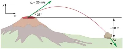
Figure 3.37 The trajectory of a rock ejected from the Kilauea volcano. Image from OpenStax College Physics 2e, CC-BY 4.0
Image Description
The image depicts a diagram of a volcanic eruption scenario with a projectile motion path. It shows a volcano on the left side, with the top emitting a projectile. The projectile is moving in a parabolic trajectory.
- Projectile Information:
- Initial velocity (\(v_0\)): 25 m/s
- Launch angle: 35 degrees above the horizontal
- Path:
- The projectile follows a red, curved path, indicating its trajectory.
- Final Point:
- The projectile lands to the right of the volcano, 20 meters below the launch point.
- The final velocity vector (\(v\)) is shown at the landing point.
- Axes:
- A coordinate system is shown, with an x-axis (horizontal) and y-axis (vertical).
Strategy
Again, resolving this two-dimensional motion into two independent one-dimensional motions will allow us to solve for the desired quantities. The time a projectile is in the air is governed by its vertical motion alone. We will solve for [latex]t[/latex] first. While the rock is rising and falling vertically, the horizontal motion continues at a constant velocity. This example asks for the final velocity. Thus, the vertical and horizontal results will be recombined to obtain [latex]v[/latex] and [latex]\theta_{v}[/latex] at the final time [latex]t[/latex] determined in the first part of the example.
Solution for (a)
While the rock is in the air, it rises and then falls to a final position 20.0 m lower than its starting altitude. We can find the time for this by using
[latex]y = y_{0} + v_{0 y} t - \frac{1}{2} \text{gt}^{2} .[/latex]
If we take the initial position [latex]y_{0}[/latex] to be zero, then the final position is [latex]y = - \text{20} .\text{0 m} .[/latex] Now the initial vertical velocity is the vertical component of the initial velocity, found from [latex]v_{0 y} = v_{0} \text{sin} \theta_{0}[/latex] = ([latex]\text{25} . \text{0}\textrm{ }\text{m}/\text{s}[/latex])([latex]\text{sin 35}.\text{0}º[/latex]) = [latex]\text{14} . \text{3}\textrm{ }\text{m}/\text{s}[/latex]. Substituting known values yields
[latex]- \text{20} . 0 m = \left(\right. \text{14} . 3 m/s \left.\right) t - \left(4 . \text{90 m}/\text{s} ^{2}\right) t^{2} .[/latex]
Rearranging terms gives a quadratic equation in [latex]t[/latex]:
[latex]\left(4 . \text{90 m}/\text{s} ^{2}\right) t^{2} - \left(\text{14} . \text{3 m}/\text{s}\right) t - \left(\text{20}.\text{0 m}\right) = 0.[/latex]
This expression is a quadratic equation of the form [latex]at^{2} + bt + c = 0[/latex], where the constants are [latex]a = 4.90[/latex], [latex]b = – 14.3[/latex], and [latex]c = – 20.0.[/latex] Its solutions are given by the quadratic formula:
[latex]t = \frac{- b \pm \sqrt{b^{2} - 4 \text{ac}}}{\text{2} \text{a}} .[/latex]
This equation yields two solutions:
[latex]t = 3.96[/latex] and [latex]t = – 1.03[/latex]. (It is left as an exercise for the reader to verify these solutions.) The time is [latex]t = 3.96 \text{s}[/latex] or [latex]– 1.03 \text{s}[/latex]. The negative value of time implies an event before the start of motion, and so we discard it. Thus,
[latex]t = 3 . \text{96 s} .[/latex]
Discussion for (a)
The time for projectile motion is completely determined by the vertical motion. So any projectile that has an initial vertical velocity of 14.3 m/s and lands 20.0 m below its starting altitude will spend 3.96 s in the air.
Solution for (b)
From the information now in hand, we can find the final horizontal and vertical velocities [latex]v_{x}[/latex] and [latex]v_{y}[/latex] and combine them to find the total velocity [latex]v[/latex] and the angle [latex]\theta_{0}[/latex] it makes with the horizontal. Of course, [latex]v_{x}[/latex] is constant so we can solve for it at any horizontal location. In this case, we chose the starting point since we know both the initial velocity and initial angle. Therefore:
[latex]v_{x} = v_{0} \text{cos} \theta_{0} = \left(\right. \text{25} . 0 m/s \left.\right) \left(\right. \text{cos 35}º \left.\right) = \text{20} . 5 m/s.[/latex]
The final vertical velocity is given by the following equation:
[latex]v_{y} = v_{0 y} - \text{gt},[/latex]
where [latex]v_{0y}[/latex] was found in part (a) to be [latex]\text{14} . \text{3}\textrm{ }\text{m}/\text{s}[/latex]. Thus,
[latex]v_{y} = \text{14} . 3 m/s - \left(\right. 9 . \text{80 m}/\text{s} ^{2} \left.\right) \left(\right. 3 . \text{96 s} \left.\right)[/latex]
so that
[latex]v_{y} = - \text{24} . 5 m/s.[/latex]
To find the magnitude of the final velocity [latex]v[/latex] we combine its perpendicular components, using the following equation:
[latex]v = \sqrt{v_{x}^{2} + v_{y}^{2}} = \sqrt{\left(\right. \text{20} . 5 m/s \left.\right)^{2} + \left(\right. - \text{24} . 5 m/s \left.\right)^{2}} ,[/latex]
which gives
[latex]v = \text{31} . 9 m/s.[/latex]
The direction [latex]\theta_{v}[/latex] is found from the equation:
[latex]\theta_{v} = \text{tan}^{- 1} \left(\right. v_{y} / v_{x} \left.\right)[/latex]
so that
[latex]\theta_{v} = \text{tan}^{- 1} \left(\right. - \text{24} . 5 / \text{20} . 5 \left.\right) = \text{tan}^{- 1} \left(\right. - 1 . \text{19} \left.\right) .[/latex]
Thus,
[latex]\theta_{v} = - \text{50} . 1 o .[/latex]
Discussion for (b)
The negative angle means that the velocity is [latex]\text{50} . 1º[/latex] below the horizontal. This result is consistent with the fact that the final vertical velocity is negative and hence downward—as you would expect because the final altitude is 20.0 m lower than the initial altitude. (See Figure 3.37.)
One of the most important things illustrated by projectile motion is that vertical and horizontal motions are independent of each other. Galileo was the first person to fully comprehend this characteristic. He used it to predict the range of a projectile. On level ground, we define range to be the horizontal distance [latex]R[/latex] traveled by a projectile. Galileo and many others were interested in the range of projectiles primarily for military purposes—such as aiming cannons. However, investigating the range of projectiles can shed light on other interesting phenomena, such as the orbits of satellites around the Earth. Let us consider projectile range further.
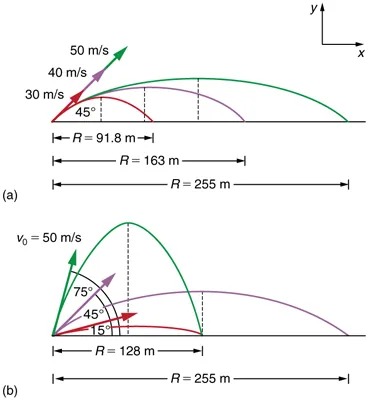
Figure 3.38 Trajectories of projectiles on level ground. (a) The greater the initial speed [latex]v_{0}[/latex], the greater the range for a given initial angle. (b) The effect of initial angle [latex]\theta_{0}[/latex] on the range of a projectile with a given initial speed. Note that the range is the same for [latex]\text{15}º[/latex] and [latex]\text{75}º[/latex], although the maximum heights of those paths are different. Image from OpenStax College Physics 2e, CC-BY 4.0
Image Description
The image consists of two diagrams showing projectile motion on a graph with different launch angles. Each diagram includes vectors, angle measurements, and horizontal distances.
Diagram (a):
– Three projectiles are launched with velocities of 30 m/s, 40 m/s, and 50 m/s from the same point.
– The projectile paths are represented in three different colors, each following a parabolic trajectory.
– The angles of launch for each projectile are marked as 45°, which indicates optimal launch angle for maximum range.
– Horizontal distances are labeled as:
– First distance: \( R = 91.8 \, \text{m} \)
– Second distance: \( R = 163 \, \text{m} \)
– Total distance to farthest point of impact: \( R = 255 \, \text{m} \)
Diagram (b):
– A single projectile is launched with an initial velocity (\( v_0 \)) of 50 m/s.
– The launch angles are varied: 75°, 45°, and 15°, each resulting in different trajectories.
– Horizontal distance for one marked trajectory: \( R = 128 \, \text{m} \)
– Total distance for the farthest trajectory: \( R = 255 \, \text{m} \)
Additional Features:
– Both diagrams include an \(x\)-\(y\) axis to indicate direction and position.
– The angles and trajectories visually compare how different launch heights and angles affect the range of a projectile.
This image illustrates the principles of projectile motion in physics, highlighting how velocity and angle of launch affect the range of a projectile.
How does the initial velocity of a projectile affect its range? Obviously, the greater the initial speed [latex]v_{0}[/latex], the greater the range, as shown in Figure 3.38(a). The initial angle [latex]\theta_{0}[/latex] also has a dramatic effect on the range, as illustrated in Figure 3.38(b). For a fixed initial speed, such as might be produced by a cannon, the maximum range is obtained with [latex]\theta_{0} = \text{45}º[/latex]. This is true only for conditions neglecting air resistance. If air resistance is considered, the maximum angle is approximately [latex]\text{38}º[/latex]. Interestingly, for every initial angle except [latex]\text{45}º[/latex], there are two angles that give the same range—the sum of those angles is [latex]\text{90}º[/latex]. The range also depends on the value of the acceleration of gravity [latex]g[/latex]. The lunar astronaut Alan Shepherd was able to drive a golf ball a great distance on the Moon because gravity is weaker there. The range [latex]R[/latex] of a projectile on level ground for which air resistance is negligible is given by
[latex]R = \frac{v_{0}^{2} \text{sin} \left(2 \theta\right)_{0}}{g} ,[/latex]
where [latex]v_{0}[/latex] is the initial speed and [latex]\theta_{0}[/latex] is the initial angle relative to the horizontal. The proof of this equation is left as an end-of-chapter problem (hints are given), but it does fit the major features of projectile range as described.
When we speak of the range of a projectile on level ground, we assume that [latex]R[/latex] is very small compared with the circumference of the Earth. If, however, the range is large, the Earth curves away below the projectile and acceleration of gravity changes direction along the path. The range is larger than predicted by the range equation given above because the projectile has farther to fall than it would on level ground. (See Figure 3.39.) If the initial speed is great enough, the projectile goes into orbit. This possibility was recognized centuries before it could be accomplished. When an object is in orbit, the Earth curves away from underneath the object at the same rate as it falls. The object thus falls continuously but never hits the surface. These and other aspects of orbital motion, such as the rotation of the Earth, will be covered analytically and in greater depth later in this text.
Once again we see that thinking about one topic, such as the range of a projectile, can lead us to others, such as the Earth orbits. In 3.5 Addition of Velocities, we will examine the addition of velocities, which is another important aspect of two-dimensional kinematics and will also yield insights beyond the immediate topic.
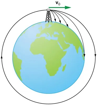
Figure 3.39 Hypothetical projectile to satellite. From this theoretical tower, a projectile is launched from a very high tower to avoid air resistance. With increasing initial speed, the range increases and becomes longer than it would be on level ground because the Earth curves away underneath its path. With a large enough initial speed, orbit is achieved. Image from OpenStax College Physics 2e, CC-BY 4.0
Image Description
The image is a diagram illustrating the concept of projectile motion and orbital paths around the Earth. It shows a representation of Earth, which is a predominantly blue circle with some green landmasses indicating continents.
At the top of the diagram, there is a small tower-like structure, positioned at the edge of Earth’s atmosphere. From this structure, multiple curved arrows are depicted. Each arrow represents a different trajectory that an object might take if launched from this point with varying initial velocities.
– The arrows are labeled with the velocities, starting with a small arc that quickly descends back to Earth, and progressively longer and higher arcs.
– The final arrow forms a complete circle around the Earth, suggesting a trajectory that achieves orbit.
– A green arrow labeled “v₀” points horizontally from the tower, indicating the initial velocity direction needed to achieve these paths.
The arcs visually demonstrate how increasing the launch velocity can change an object’s trajectory from a short-range path to a long-range or even orbital path around the planet.
PhET Explorations
Projectile Motion
Blast a Buick out of a cannon! Learn about projectile motion by firing various objects. Set the angle, initial speed, and mass. Add air resistance. Make a game out of this simulation by trying to hit a target.
