Conceptual Questions
Conceptual Questions
16.1 Current
- Can a wire carry a current and still be neutral—that is, have a total charge of zero? Explain.
- Car batteries are rated in ampere-hours ([latex]\text{A} \cdot \text{h}[/latex]). To what physical quantity do ampere-hours correspond (voltage, charge, . . .), and what relationship do ampere-hours have to energy content?
- If two different wires having identical cross-sectional areas carry the same current, will the drift velocity be higher or lower in the better conductor? Explain in terms of the equation [latex]v_{\text{d}} = \frac{I}{\text{nqA}}[/latex], by considering how the density of charge carriers [latex]n[/latex] relates to whether or not a material is a good conductor.
- Why are two conducting paths from a voltage source to an electrical device needed to operate the device?
- In cars, one battery terminal is connected to the metal body. How does this allow a single wire to supply current to electrical devices rather than two wires?
- Why isn’t a bird sitting on a high-voltage power line electrocuted? Contrast this with the situation in which a large bird hits two wires simultaneously with its wings.
16.2 Ohm’s Law: Resistance and Simple Circuits
- The [latex]\text{IR}[/latex] drop across a resistor means that there is a change in potential or voltage across the resistor. Is there any change in current as it passes through a resistor? Explain.
- How is the [latex]\text{IR}[/latex] drop in a resistor similar to the pressure drop in a fluid flowing through a pipe?
16.3 Resistance and Resistivity
- In which of the three semiconducting materials listed in Table 16.1 do impurities supply free charges? (Hint: Examine the range of resistivity for each and determine whether the pure semiconductor has the higher or lower conductivity.)
- Does the resistance of an object depend on the path current takes through it? Consider, for example, a rectangular bar—is its resistance the same along its length as across its width? (See Figure 16.38.)
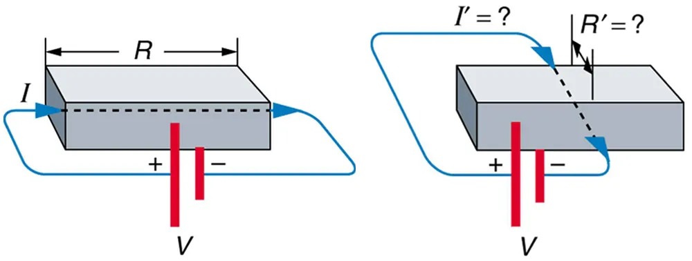
Figure 16.38 Does current taking two different paths through the same object encounter different resistance? Image from OpenStax College Physics 2e, CC-BY 4.0
Image Description
The image consists of two diagrams of a rectangular block representing circuits with voltage and current configurations.
Left Diagram:
– A rectangular block is shown with a current “I” entering from the left side.
– The top of the block is annotated with “R,” indicating resistance.
– Two vertical red lines with a “+” and “−” sign denote voltage “V” across the block.
– A blue wire forms a loop around the block, representing the flow of current.
Right Diagram:
– Similar to the left diagram, another rectangular block is shown.
– Current “I'” and resistance “R'” are marked with a question mark.
– The “+” and “−” voltage “V” remains the same on the red vertical lines.
– A dashed line on the top indicates a change in resistance.
– A blue wire loop illustrates the current flow.
This demonstrates a comparison between two different configurations of current and resistance across a similar medium with the same voltage applied.
- If aluminum and copper wires of the same length have the same resistance, which has the larger diameter? Why?
- Explain why [latex]R = R_{0} \left(\right. \text{1 } + \alpha Δ T \left.\right)[/latex] for the temperature variation of the resistance [latex]R[/latex] of an object is not as accurate as [latex]\rho = \rho_{0} \left(\right. \text{1 } + \alpha Δ T \left.\right)[/latex], which gives the temperature variation of resistivity [latex]\rho[/latex].
16.4 Electric Power and Energy
- Why do incandescent lightbulbs grow dim late in their lives, particularly just before their filaments break?
- The power dissipated in a resistor is given by [latex]P = V^{2} / R[/latex], which means power decreases if resistance increases. Yet this power is also given by [latex]P = I^{2} R[/latex], which means power increases if resistance increases. Explain why there is no contradiction here.
16.5 Alternating Current versus Direct Current
- Give an example of a use of AC power other than in the household. Similarly, give an example of a use of DC power other than that supplied by batteries.
- Why do voltage, current, and power go through zero 120 times per second for 60-Hz AC electricity?
- You are riding in a train, gazing into the distance through its window. As close objects streak by, you notice that the nearby fluorescent lights make dashed streaks. Explain.
16.6 Electric Hazards and the Human Body
- Using an ohmmeter, a student measures the resistance between various points on his body. They find that the resistance between two points on the same finger is about the same as the resistance between two points on opposite hands—both are several hundred thousand ohms. Furthermore, the resistance decreases when more skin is brought into contact with the probes of the ohmmeter. Finally, there is a dramatic drop in resistance (to a few thousand ohms) when the skin is wet. Explain these observations and their implications regarding skin and internal resistance of the human body.
- What are the two major hazards of electricity?
- Why isn’t a short circuit a shock hazard?
- What determines the severity of a shock? Can you say that a certain voltage is hazardous without further information?
- An electrified needle is used to burn off warts, with the circuit being completed by having the patient sit on a large butt plate. Why is this plate large?
- Some surgery is performed with high-voltage electricity passing from a metal scalpel through the tissue being cut. Considering the nature of electric fields at the surface of conductors, why would you expect most of the current to flow from the sharp edge of the scalpel? Do you think high- or low-frequency AC is used?
- Some devices often used in bathrooms, such as hairdryers, often have safety messages saying “Do not use when the bathtub or basin is full of water.” Why is this so?
- We are often advised to not flick electric switches with wet hands, dry your hand first. We are also advised to never throw water on an electric fire. Why is this so?
- Before working on a power transmission line, experts will touch the line with the back of the hand as a final check that the voltage is zero. Why the back of the hand?
- Why is the resistance of wet skin so much smaller than dry, and why do blood and other bodily fluids have low resistances?
- Could a person on intravenous infusion (an IV) be microshock sensitive?
- In view of the small currents that cause shock hazards and the larger currents that circuit breakers and fuses interrupt, how do they play a role in preventing shock hazards?
16.7 Nerve Conduction–Electrocardiograms
- Note that in Figure 16.25, both the concentration gradient and the Coulomb force tend to move [latex]\text{Na}^{+ }[/latex] ions into the cell. What prevents this?
- Define depolarization, repolarization, and the action potential.
- Explain the properties of myelinated nerves in terms of the insulating properties of myelin.
16.8 Resistors in Series and Parallel
- A switch has a variable resistance that is nearly zero when closed and extremely large when open, and it is placed in series with the device it controls. Explain the effect the switch in Figure 16.39 has on current when open and when closed.
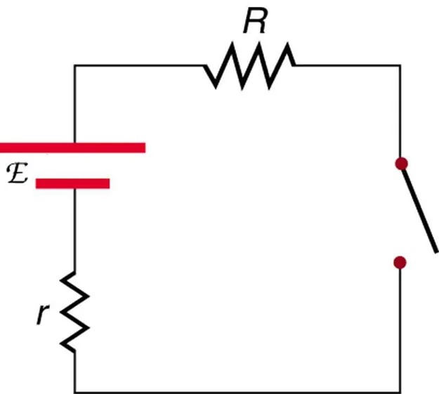
Figure 16.39 A switch is ordinarily in series with a resistance and voltage source. Ideally, the switch has nearly zero resistance when closed but has an extremely large resistance when open. Image from OpenStax College Physics 2e, CC-BY 4.0
Image Description
The image shows a simple electrical circuit diagram. The main components include:
– A voltage source on the left, represented by two parallel lines, where the longer line is marked with “E” and the shorter with “r”.
– A resistor labeled “R” is located at the top of the circuit.
– A switch is depicted on the right side, shown in an open position, represented by two small circles connected by a line which is tilted to signify the open state.
– The wires connecting these components form a rectangular loop, completing the circuit.
The diagram illustrates the basic elements of an electrical circuit with an internal resistance “r” and an external resistor “R”, while the switch is currently open, indicating that the circuit is not complete.
- What is the voltage across the open switch in Figure 16.39?
- There is a voltage across an open switch, such as in Figure 16.39. Why, then, is the power dissipated by the open switch small? Why is the power dissipated by a closed switch, such as in Figure 16.39, small?
- A student in a physics lab mistakenly wired a light bulb, battery, and switch as shown in Figure 16.40. Explain why the bulb is on when the switch is open, and off when the switch is closed. (Do not try this—it is hard on the battery!)
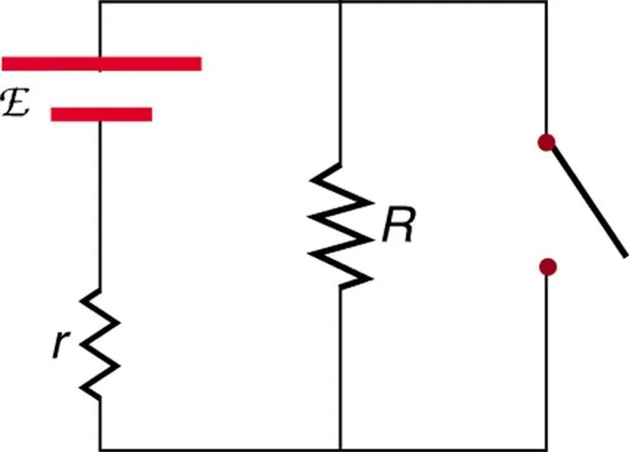
Figure 16.40 A wiring mistake put this switch in parallel with the device represented by [latex]R[/latex]. Image from OpenStax College Physics 2e, CC-BY 4.0
Image Description
The image depicts an electrical circuit diagram consisting of a battery and resistors. On the left, there is a symbol for an ideal battery with an electromotive force labeled as ℰ. Below it, there is a resistor labeled r, representing the internal resistance of the battery. The circuit splits into two parallel branches: one contains a large zigzag line resistor labeled R, and the other includes a closed switch. Red dots indicate connection points in the circuit where the wires and components are joined.
- Knowing that the severity of a shock depends on the magnitude of the current through your body, would you prefer to be in series or parallel with a resistance, such as the heating element of a toaster, if shocked by it? Explain.
- Would your headlights dim when you start your car’s engine if the wires in your automobile were superconductors? (Do not neglect the battery’s internal resistance.) Explain.
