Problems & Exercises
Problems & Exercises
15.1 Static Electricity and Charge: Conservation of Charge
- Common static electricity involves charges ranging from nanocoulombs to microcoulombs. (a) How many electrons are needed to form a charge of [latex]–2.00 \text{nC}[/latex] (b) How many electrons must be removed from a neutral object to leave a net charge of [latex]0.500 \mu \text{C}[/latex]?
- If [latex]1 . \text{80} \times \text{10}^{\text{20}}[/latex] electrons move through a pocket calculator during a full day’s operation, how many coulombs of charge moved through it?
- To start a car engine, the car battery moves [latex]3 . \text{75} \times \text{10}^{\text{21}}[/latex] electrons through the starter motor. How many coulombs of charge were moved?
- A certain lightning bolt moves 40.0 C of charge. How many fundamental units of charge [latex]\mid q_{e} \mid[/latex] is this?
15.2 Conductors and Insulators
- Suppose a speck of dust in an electrostatic precipitator has [latex]1 . \text{0000} \times \text{10}^{\text{12}}[/latex] protons in it and has a net charge of –5.00 nC (a very large charge for a small speck). How many electrons does it have?
- An amoeba has [latex]1.00 \times 10^{16}[/latex] protons and a net charge of 0.300 pC. (a) How many fewer electrons are there than protons? (b) If you paired them up, what fraction of the protons would have no electrons?
- A 50.0 g ball of copper has a net charge of [latex]2.00 \mu \text{C}[/latex]. What fraction of the copper’s electrons has been removed? (Each copper atom has 29 protons, and copper has an atomic mass of 63.5.)
- What net charge would you place on a 100 g piece of sulfur if you put an extra electron on 1 in [latex]\text{10}^{\text{12}}[/latex] of its atoms? (Sulfur has an atomic mass of 32.1.)
- How many coulombs of positive charge are there in 4.00 kg of plutonium, given its atomic mass is 244 and that each plutonium atom has 94 protons?
15.3 Coulomb’s Law
- What is the repulsive force between two pith balls that are 8.00 cm apart and have equal charges of – 30.0 nC?
- (a) How strong is the attractive force between a glass rod with a [latex]0.700 \mu \text{C}[/latex] charge and a silk cloth with a [latex]–0.600 \mu \text{C}[/latex] charge, which are 12.0 cm apart, using the approximation that they act like point charges? (b) Discuss how the answer to this problem might be affected if the charges are distributed over some area and do not act like point charges.
- Two point charges exert a 5.00 N force on each other. What will the force become if the distance between them is increased by a factor of three?
- Two point charges are brought closer together, increasing the force between them by a factor of 25. By what factor was their separation decreased?
- How far apart must two point charges of 75.0 nC (typical of static electricity) be to have a force of 1.00 N between them?
- If two equal charges each of 1 C each are separated in air by a distance of 1 km, what is the magnitude of the force acting between them? You will see that even at a distance as large as 1 km, the repulsive force is substantial because 1 C is a very significant amount of charge.
- A test charge of [latex]+2 \mu \text{C}[/latex] is placed halfway between a charge of [latex]+6 \mu \text{C}[/latex] and another of [latex]+4 \mu \text{C}[/latex] separated by 10 cm. (a) What is the magnitude of the force on the test charge? (b) What is the direction of this force (away from or toward the [latex]+6 \mu \text{C}[/latex] charge)?
- Bare free charges do not remain stationary when close together. To illustrate this, calculate the acceleration of two isolated protons separated by 2.00 nm (a typical distance between gas atoms). Explicitly show how you follow the steps in the Problem-Solving Strategy for electrostatics.
- (a) By what factor must you change the distance between two point charges to change the force between them by a factor of 10? (b) Explain how the distance can either increase or decrease by this factor and still cause a factor of 10 change in the force.
- Suppose you have a total charge [latex]q_{\text{tot}}[/latex] that you can split in any manner. Once split, the separation distance is fixed. How do you split the charge to achieve the greatest force?
- (a) Common transparent tape becomes charged when pulled from a dispenser. If one piece is placed above another, the repulsive force can be great enough to support the top piece’s weight. Assuming equal point charges (only an approximation), calculate the magnitude of the charge if electrostatic force is great enough to support the weight of a 10.0 mg piece of tape held 1.00 cm above another. (b) Discuss whether the magnitude of this charge is consistent with what is typical of static electricity.
- (a) Find the ratio of the electrostatic to gravitational force between two electrons. (b) What is this ratio for two protons? (c) Why is the ratio different for electrons and protons?
- At what distance is the electrostatic force between two protons equal to the weight of one proton?
- A certain five cent coin contains 5.00 g of nickel. What fraction of the nickel atoms’ electrons, removed and placed 1.00 m above it, would support the weight of this coin? The atomic mass of nickel is 58.7, and each nickel atom contains 28 electrons and 28 protons.
- (a) Two point charges totaling [latex]8.00 \mu \text{C}[/latex] exert a repulsive force of 0.150 N on one another when separated by 0.500 m. What is the charge on each? (b) What is the charge on each if the force is attractive?
- Point charges of [latex]5.00 \mu \text{C}[/latex] and [latex]–3.00 \mu \text{C}[/latex] are placed 0.250 m apart. (a) Where can a third charge be placed so that the net force on it is zero? (b) What if both charges are positive?
- Two point charges [latex]q_{\text{1}}[/latex] and [latex]q_{\text{2}}[/latex] are [latex]3.00 m[/latex] apart, and their total charge is [latex]20 \mu \text{C}[/latex]. (a) If the force of repulsion between them is 0.075N, what are magnitudes of the two charges? (b) If one charge attracts the other with a force of 0.525N, what are the magnitudes of the two charges? Note that you may need to solve a quadratic equation to reach your answer.
15.4 Electric Field: Concept of a Field Revisited
- What is the magnitude and direction of an electric field that exerts a [latex]2 . \text{00} \times \text{10}^{- 5} \text{N}[/latex] upward force on a [latex]–1.75 \mu \text{C}[/latex] charge?
- What is the magnitude and direction of the force exerted on a [latex]3.50 \mu \text{C}[/latex] charge by a 250 N/C electric field that points due east?
- Calculate the magnitude of the electric field 2.00 m from a point charge of 5.00 mC (such as found on the terminal of a Van de Graaff).
- (a) What magnitude point charge creates a 10,000 N/C electric field at a distance of 0.250 m? (b) How large is the field at 10.0 m?
- Calculate the initial (from rest) acceleration of a proton in a [latex]5 . \text{00} \times \text{10}^{6} \text{N}/\text{C}[/latex] electric field (such as created by a research Van de Graaff). Explicitly show how you follow the steps in the Problem-Solving Strategy for electrostatics.
- (a) Find the magnitude and direction of an electric field that exerts a [latex]4 . \text{80} \times \text{10}^{- \text{17}} \text{N}[/latex] westward force on an electron. (b) What magnitude and direction force does this field exert on a proton?
15.5 Electric Field Lines: Multiple Charges
- (a) Sketch the electric field lines near a point charge [latex]+ q[/latex]. (b) Do the same for a point charge [latex]–3.00 q[/latex].
- Sketch the electric field lines a long distance from the charge distributions shown in Figure 15.23 (a) and (b)
- Figure 15.43 shows the electric field lines near two charges [latex]q_{1}[/latex] and [latex]q_{2}[/latex]. What is the ratio of their magnitudes? (b) Sketch the electric field lines a long distance from the charges shown in the figure.
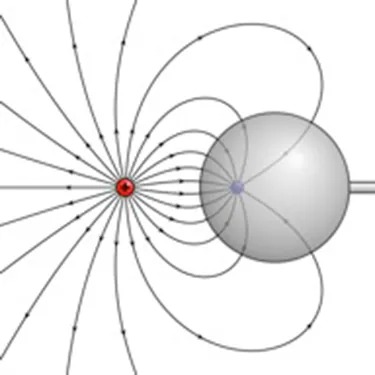
Figure 15.43 The electric field near two charges. Image by Geek3, Wikimedia Commons License
Image Description
The image depicts a diagram showing magnetic field lines. On the left side, there is a small red circle with a tiny black dot at its center, representing a magnetic pole. Emanating from this circle are numerous curved black lines that extend outward in all directions. These lines curve around a large gray sphere on the right side of the image. The gray sphere has a smaller purple circle on its left side, possibly indicating another magnetic pole on the sphere. The lines illustrate the magnetic flux and their interaction with the sphere, showing how the field lines are distorted around the sphere. No text or labels are present in the image.
- Sketch the electric field lines in the vicinity of two opposite charges, where the negative charge is three times greater in magnitude than the positive. (See Figure 15.43 for a similar situation).
15.7 Conductors and Electric Fields in Static Equilibrium
- Sketch the electric field lines in the vicinity of the conductor in Figure 15.44 given the field was originally uniform and parallel to the object’s long axis. Is the resulting field small near the long side of the object?
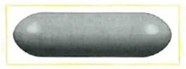
Figure 15.44 Image from OpenStax College Physics 2e, CC-BY 4.0
Image Description
The image shows a single, elongated, oval-shaped object with a smooth surface. The object is light gray in color. It is horizontally oriented and appears within a yellow rectangular border. The lighting creates a slight reflection on the top surface of the object, indicating a glossy texture.
- Sketch the electric field lines in the vicinity of the conductor in Figure 15.45 given the field was originally uniform and parallel to the object’s long axis. Is the resulting field small near the long side of the object?
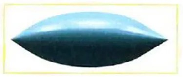
Figure 15.45 Image from OpenStax College Physics 2e, CC-BY 4.0
Image Description
A blue, elongated, oval-shaped object resembling a 3D geometric form that tapers at both ends, similar to an inflated cushion or pill. It is centered on a plain white background, creating a stark contrast with its smooth, shiny surface.
- Sketch the electric field between the two conducting plates shown in Figure 15.46, given the top plate is positive and an equal amount of negative charge is on the bottom plate. Be certain to indicate the distribution of charge on the plates.
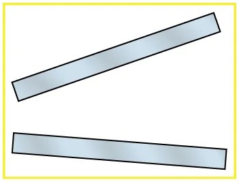
Figure 15.46 Image from OpenStax College Physics 2e, CC-BY 4.0
Image Description
The image shows two long, narrow rectangles positioned diagonally on a white background. The rectangles have a slight gradient suggesting they are metallic or reflective, with black outlines. The top rectangle is angled slightly upwards from left to right, while the bottom rectangle is angled slightly downwards from left to right. The entire image is bordered by a thin yellow line.
- Sketch the electric field lines in the vicinity of the charged insulator in Figure 15.47 noting its nonuniform charge distribution.
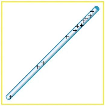
Figure 15.47 A charged insulating rod such as might be used in a classroom demonstration. Image from OpenStax College Physics 2e, CC-BY 4.0
Image Description
The image shows a long, cylindrical object, resembling a light blue rod, positioned diagonally across the image. The rod has a series of black crosses evenly spaced along its length. The entire image is bordered by a thin, yellow line.
- What is the force on the charge located at [latex]x = 8.00 cm[/latex] in Figure 15.48(a) given that [latex]q = 1 . \text{00} \mu\text{C}[/latex]?
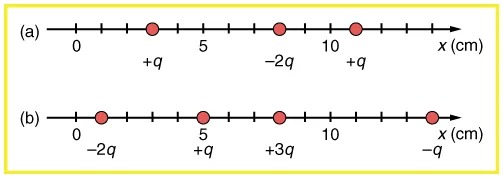
Figure 15.48 (a) Point charges located at 3.00, 8.00, and 11.0 cm along the x-axis. (b) Point charges located at 1.00, 5.00, 8.00, and 14.0 cm along the x-axis. Image from OpenStax College Physics 2e, CC-BY 4.0
Image Description
The image consists of two diagrams labeled (a) and (b), each having a straight horizontal line with evenly spaced tick marks along the x-axis, marked in centimeters (cm). Both diagrams include red dots positioned at specific intervals, representing charges with magnitude and sign.
Diagram (a):
- The horizontal axis is labeled x (cm).
- There are four red dots placed at the following positions:
- At 0 cm, labeled with charge +q.
- At 5 cm.
- At 10 cm, labeled with charge -2q.
- Beyond 10 cm, labeled with charge +q.
Diagram (b):
- The horizontal axis is labeled x (cm).
- There are four red dots placed at the following positions:
- At 0 cm, labeled with charge -2q.
- At 5 cm, labeled with charge +q.
- At 10 cm, labeled with charge +3q.
- Beyond 10 cm, labeled with charge -q.
- (a) Find the total electric field at [latex]x = 1.00 cm[/latex] in Figure 15.48(b) given that [latex]q = 5.00 nC[/latex]. (b)Find the total electric field at [latex]x = 11.00 cm[/latex] in Figure 15.48(b) given that [latex]q = 5.00 nC[/latex]. (c) If the charges are allowed to move and eventually be brought to rest by friction, what will the final charge configuration be? (That is, will there be a single charge, double charge, etc., and what will its value(s) be?)
- (a) Find the electric field at [latex]x = 5.00 cm[/latex] in Figure 15.48(a), given that [latex]q = 1.00 \mu\text{C}[/latex]. (b) At what position between 3.00 and 8.00 cm is the total electric field the same as that for [latex]–2 q[/latex] alone? (c) Can the electric field be zero anywhere between 0.00 and 8.00 cm? (d) At very large positive or negative values of x, the electric field approaches zero in both (a) and (b). In which does it most rapidly approach zero and why? (e) At what position to the right of 11.0 cm is the total electric field zero, other than at infinity? (Hint: A graphing calculator can yield considerable insight in this problem.)
- (a) Find the total Coulomb force on a charge of 2.00 nC located at [latex]x = 4.00 cm[/latex] in Figure 15.48 (b), given that [latex]q = 1.00 \mu\text{C}[/latex]. (b) Find the x-position at which the electric field is zero in Figure 15.48 (b).
- Using the symmetry of the arrangement, determine the direction of the force on [latex]q[/latex] in the figure below, given that [latex]q_{a} = q_{b} =+ 7 . \text{50} \mu\text{C}[/latex] and [latex]q_{c} = q_{d} = - 7 . \text{50} \mu\text{C}[/latex]. (b) Calculate the magnitude of the force on the charge [latex]q[/latex], given that the square is 10.0 cm on a side and [latex]q = 2 . \text{00} \mu\text{C}[/latex].
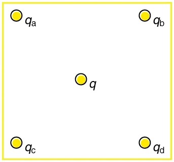
Figure 15.49 Image from OpenStax College Physics 2e, CC-BY 4.0
Image Description
The image is a diagram showing five yellow circles enclosed within a yellow square outline. Four circles are positioned at each corner of the square, labeled as “qa” in the top-left, “qb” in the top-right, “qc” in the bottom-left, and “qd” in the bottom-right. There is one circle located at the center of the square labeled as “q.” Each circle has a black outline.
- (a) Using the symmetry of the arrangement, determine the direction of the electric field at the center of the square in Figure 15.49, given that [latex]q_{a} = q_{b} = - 1 . \text{00} \mu\text{C}[/latex] and [latex]q_{c} = q_{d} =+ 1 . \text{00} \mu\text{C}[/latex]. (b) Calculate the magnitude of the electric field at the location of [latex]q[/latex], given that the square is 5.00 cm on a side.
- Find the electric field at the location of [latex]q_{a}[/latex] in Figure 15.49 given that [latex]q_{b} = q_{c} = q_{d} =+ 2 . \text{00} \text{nC}[/latex], [latex]q = - 1 . \text{00} \text{nC}[/latex], and the square is 20.0 cm on a side.
- Find the total Coulomb force on the charge [latex]q[/latex] in Figure 15.49, given that [latex]q = 1 . \text{00} \mu\text{C}[/latex], [latex]q_{a} = 2 . \text{00} \mu\text{C}[/latex], [latex]q_{b} = - 3 . \text{00} \mu\text{C}[/latex], [latex]q_{c} = - 4 . \text{00} \mu\text{C}[/latex], and [latex]q_{d} =+ 1 . \text{00} \mu\text{C}[/latex]. The square is 50.0 cm on a side.
- (a) Find the electric field at the location of [latex]q_{a}[/latex] in Figure 15.50, given that [latex]q_{\text{b}} = +10.00 \mu \text{C}[/latex] and [latex]q_{\text{c}} = –5.00 \mu \text{C}[/latex]. (b) What is the force on [latex]q_{a}[/latex], given that [latex]q_{\text{a}} = +1.50 \text{nC}[/latex]?
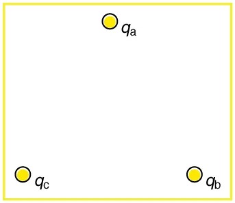
Figure 15.50 Point charges located at the corners of an equilateral triangle 25.0 cm on a side. Image from OpenStax College Physics 2e, CC-BY 4.0
Image Description
The image shows a simple diagram consisting of three small yellow circles, each labeled with a different subscript letter. These circles are distributed at the corners of an imaginary triangle inside the larger white square with a thin yellow border.
- The top circle is labeled “qa“.
- The bottom right circle is labeled “qb“.
- The bottom left circle is labeled “qc“.
- (a) Find the electric field at the center of the triangular configuration of charges in Figure 15.50, given that [latex]q_{a} =+ 2 . \text{50} \text{nC}[/latex], [latex]q_{b} = - 8 . \text{00} \text{nC}[/latex], and [latex]q_{c} =+ 1 . \text{50} \text{nC}[/latex]. (b) Is there any combination of charges, other than [latex]q_{a} = q_{b} = q_{c}[/latex], that will produce a zero strength electric field at the center of the triangular configuration?
15.8 Applications of Electrostatics
- (a) What is the electric field 5.00 m from the center of the terminal of a Van de Graaff with a 3.00 mC charge, noting that the field is equivalent to that of a point charge at the center of the terminal? (b) At this distance, what force does the field exert on a [latex]2.00 \mu \text{C}[/latex] charge on the Van de Graaff’s belt?
- (a) What is the direction and magnitude of an electric field that supports the weight of a free electron near the surface of Earth? (b) Discuss what the small value for this field implies regarding the relative strength of the gravitational and electrostatic forces.
- A simple and common technique for accelerating electrons is shown in Figure 15.51, where there is a uniform electric field between two plates. Electrons are released, usually from a hot filament, near the negative plate, and there is a small hole in the positive plate that allows the electrons to continue moving. (a) Calculate the acceleration of the electron if the field strength is [latex]2.50 \times 10^{4} \text{N}/\text{C}[/latex]. (b) Explain why the electron will not be pulled back to the positive plate once it moves through the hole.
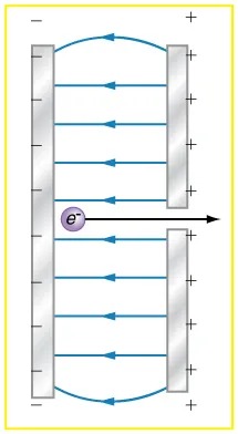
Figure 15.51 Parallel conducting plates with opposite charges on them create a relatively uniform electric field used to accelerate electrons to the right. Those that go through the hole can be used to make a TV or computer screen glow or to produce X-rays. Image from OpenStax College Physics 2e, CC-BY 4.0
Image Description
The image shows a diagram of an electric field between two parallel metal plates. The setup includes:
– Two vertical silver-colored plates on each side with small positive and negative signs indicating polarity. The left plate is positive, and the right plate is negative.
– Blue arrows are pointing straight from the positive plate to the negative plate, indicating the direction of the electric field.
– A single electron, marked with “e⁻” inside a purple circle, is positioned between the plates. An arrow next to the electron shows its movement direction towards the right.
– The entire setup is enclosed within a yellow border.
This diagram illustrates the force acting on an electron in an electric field generated by parallel plate capacitors.
- Earth has a net charge that produces an electric field of approximately 150 N/C downward at its surface. (a) What is the magnitude and sign of the excess charge, noting the electric field of a conducting sphere is equivalent to a point charge at its center? (b) What acceleration will the field produce on a free electron near Earth’s surface? (c) What mass object with a single extra electron will have its weight supported by this field?
- Point charges of [latex]25.0 \mu \text{C}[/latex] and [latex]45.0 \mu \text{C}[/latex] are placed 0.500 m apart. (a) At what point along the line between them is the electric field zero? (b) What is the electric field halfway between them?
- What can you say about two charges [latex]q_{1}[/latex] and [latex]q_{2}[/latex], if the electric field one-fourth of the way from [latex]q_{1}[/latex] to [latex]q_{2}[/latex] is zero?
- Integrated Concepts: Calculate the angular velocity [latex]ω[/latex] of an electron orbiting a proton in the hydrogen atom, given the radius of the orbit is [latex]0.530 \times 10^{–10} \text{m}[/latex]. You may assume that the proton is stationary and the centripetal force is supplied by Coulomb attraction.
- Integrated Concepts: An electron has an initial velocity of [latex]5.00 \times 10^{6} \text{m}/\text{s}[/latex] in a uniform [latex]2.00 \times 10^{5} \text{N}/\text{C}[/latex] strength electric field. The field accelerates the electron in the direction opposite to its initial velocity. (a) What is the direction of the electric field? (b) How far does the electron travel before coming to rest? (c) How long does it take the electron to come to rest? (d) What is the electron’s velocity when it returns to its starting point?
- Integrated Concepts: The practical limit to an electric field in air is about [latex]3.00 \times 10^{6} \text{N}/\text{C}[/latex]. Above this strength, sparking takes place because air begins to ionize and charges flow, reducing the field. (a) Calculate the distance a free proton must travel in this field to reach [latex]3.00%[/latex] of the speed of light, starting from rest. (b) Is this practical in air, or must it occur in a vacuum?
- Integrated Concepts: A 5.00 g charged insulating ball hangs on a 30.0 cm long string in a uniform horizontal electric field as shown in Figure 15.52. Given the charge on the ball is [latex]1.00 \mu \text{C}[/latex], find the strength of the field.
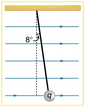
Figure 15.52 A horizontal electric field causes the charged ball to hang at an angle of [latex]8.00º[/latex]. Image from OpenStax College Physics 2e, CC-BY 4.0
Image Description
The image depicts a pendulum with a weight, labeled “q,” suspended from a horizontal wooden beam. The pendulum is shown at an angle of 8 degrees from the vertical, indicated by a dashed line representing the vertical position and a black line representing the pendulum. Several horizontal blue arrows point to the right, representing a uniform force, such as an electric field, acting on the pendulum. The background has lines evenly spaced horizontally across the image.
- Integrated Concepts: Figure 15.53 shows an electron passing between two charged metal plates that create an 100 N/C vertical electric field perpendicular to the electron’s original horizontal velocity. (These can be used to change the electron’s direction, such as in an oscilloscope.) The initial speed of the electron is [latex]3.00 \times 10^{6} \text{m}/\text{s}[/latex], and the horizontal distance it travels in the uniform field is 4.00 cm. (a) What is its vertical deflection? (b) What is the vertical component of its final velocity? (c) At what angle does it exit? Neglect any edge effects.
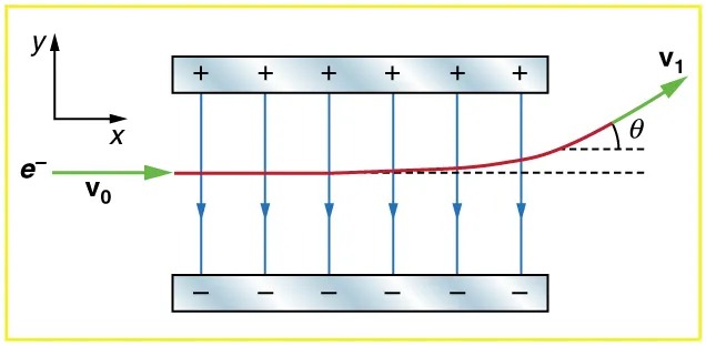
Figure 15.53 Image from OpenStax College Physics 2e, CC-BY 4.0
Image Description
The image depicts a diagram illustrating the trajectory of an electron, represented by e–, moving initially at velocity v0 towards the right. The path of the electron is marked by a red curve indicating its trajectory under the influence of an electric field. The field is represented by vertical blue arrows pointing downwards, indicating the direction of the electric force between two parallel plates. The upper plate has a positive charge, marked with plus signs, and the lower plate has a negative charge, marked with minus signs.
The electron’s path curves upward as it exits the field, with its final velocity represented by the vector v1. The angle between the initial horizontal line and the final direction of the electron is labeled as θ. An x-y coordinate system is shown at the top left corner for reference, with the x-axis pointing to the right and the y-axis pointing upward.
- Integrated Concepts: The classic Millikan oil drop experiment was the first to obtain an accurate measurement of the charge on an electron. In it, oil drops were suspended against the gravitational force by a vertical electric field. (See Figure 15.54.) Given the oil drop to be [latex]1.00 \mu \text{m}[/latex] in radius and have a density of [latex]920 kg/ m^{3}[/latex]: (a) Find the weight of the drop. (b) If the drop has a single excess electron, find the electric field strength needed to balance its weight.
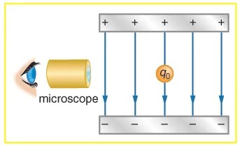
Figure 15.54 In the Millikan oil drop experiment, small drops can be suspended in an electric field by the force exerted on a single excess electron. Classically, this experiment was used to determine the electron charge [latex]q_{\text{e}}[/latex] by measuring the electric field and mass of the drop. Image from OpenStax College Physics 2e, CC-BY 4.0
Image Description
The image depicts a diagram of an experiment setup. On the left side, there is a graphic of an eye looking through a microscope. To the right of the microscope, there is an arrangement consisting of two horizontal plates, one above the other. The upper plate is marked with positive (+) signs, while the lower plate is marked with negative (-) signs, representing a uniform electric field. Vertical arrows point downward between the plates, indicating the direction of the electric field. In the center, there is a small circle labeled “q0,” representing a point charge, placed between the plates. The setup is enclosed within a yellow border.
- Integrated Concepts: (a) In Figure 15.55, four equal charges [latex]q[/latex] lie on the corners of a square. A fifth charge [latex]Q[/latex] is on a mass [latex]m[/latex] directly above the center of the square, at a height equal to the length [latex]d[/latex] of one side of the square. Determine the magnitude of [latex]q[/latex] in terms of [latex]Q[/latex], [latex]m[/latex], and [latex]d[/latex], if the Coulomb force is to equal the weight of [latex]m[/latex]. (b) Is this equilibrium stable or unstable? Discuss.
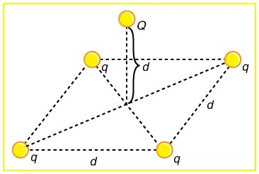
Figure 15.55 Four equal charges on the corners of a horizontal square support the weight of a fifth charge located directly above the center of the square. Image from OpenStax College Physics 2e, CC-BY 4.0
Image Description
The image depicts a geometric configuration of five points, each represented by a yellow circle, connected by dashed lines forming a network. The points are arranged as follows:
- Four points are positioned at the vertices of a quadrilateral (a four-sided shape).
- One point is labeled “Q” and is located above the center of the quadrilateral.
The connections are labeled with distances:
- The distance from the central point “Q” to the top vertex of the quadrilateral is labeled “d.”
- The distances connecting the other vertices of the quadrilateral to each other are labeled “q” and “d” as well.
The entire configuration is enclosed within a rectangle outlined with a yellow border.
- Unreasonable Results: (a) Calculate the electric field strength near a 10.0 cm diameter conducting sphere that has 1.00 C of excess charge on it. (b) What is unreasonable about this result? (c) Which assumptions are responsible?
- Unreasonable Results: (a) Two 0.500 g raindrops in a thunderhead are 1.00 cm apart when they each acquire 1.00 mC charges. Find their acceleration. (b) What is unreasonable about this result? (c) Which premise or assumption is responsible?
- Unreasonable Results: A wrecking yard inventor wants to pick up cars by charging a 0.400 m diameter ball and inducing an equal and opposite charge on the car. If a car has a 1000 kg mass and the ball is to be able to lift it from a distance of 1.00 m: (a) What minimum charge must be used? (b) What is the electric field near the surface of the ball? (c) Why are these results unreasonable? (d) Which premise or assumption is responsible?
- Construct Your Own Problem: Consider two insulating balls with evenly distributed equal and opposite charges on their surfaces, held with a certain distance between the centers of the balls. Construct a problem in which you calculate the electric field (magnitude and direction) due to the balls at various points along a line running through the centers of the balls and extending to infinity on either side. Choose interesting points and comment on the meaning of the field at those points. For example, at what points might the field be just that due to one ball and where does the field become negligibly small? Among the things to be considered are the magnitudes of the charges and the distance between the centers of the balls. Your instructor may wish for you to consider the electric field off axis or for a more complex array of charges, such as those in a water molecule.
- Construct Your Own Problem: Consider identical spherical conducting space ships in deep space where gravitational fields from other bodies are negligible compared to the gravitational attraction between the ships. Construct a problem in which you place identical excess charges on the space ships to exactly counter their gravitational attraction. Calculate the amount of excess charge needed. Examine whether that charge depends on the distance between the centers of the ships, the masses of the ships, or any other factors. Discuss whether this would be an easy, difficult, or even impossible thing to do in practice.
- Critical Thinking: A frictionless circular track with a diameter of 4.00 m has two spheres of 10.0 kg each anchored very near it. The track is oriented with a diameter along the x-axis. The anchored spheres are just outside the track. One of the anchored spheres is just left of the origin at a distance of [latex]1.00 \times 10^{- 15} \text{m}[/latex] from it, and the other is on the x-axis just right of the track at a distance of [latex]1.00 \times 10^{- 15} \text{m}[/latex] past [latex]\left(\right. 4 , 0 \left.\right)[/latex]. Each sphere carries a charge of [latex]2.00 \times 10^{- 9} \textrm{ }\text{C}[/latex]. (Note: The slight distance from the track is so the particles cannot collide, and does not enter into the calculations for three significant figures.) (a) A third sphere has a mass of 10.00 kg and carries a charge of [latex]- 1.00 \times 10^{- 9} \textrm{ }\text{C}[/latex]. It is free to move on the track. It is initially placed an equal length from the two anchored spheres at [latex]\left(\right. 2.00 , 2.00 \left.\right)[/latex]. What is the total force on the third sphere? (Be certain to include gravity between the spheres.) (b) Will the third sphere move? (c) Label the first two spheres A and B, and the movable sphere C. Now start sphere C at [latex]\left(\right. 1.00 , 2.00 \left.\right)[/latex]. What are the forces on sphere C? (d) Will sphere C now move? (e) If it does, where will it stop moving and reverse course? If it does not move, you may skip this part. (f) How many equilibrium points are there on the track at which the movable sphere will remain stationary? Where are they?
