7.5 Simple Machines
Learning Objectives
By the end of this section, you will be able to:
- Describe different simple machines.
- Calculate the mechanical advantage.
Simple machines are devices that can be used to multiply or augment a force that we apply – often at the expense of a distance through which we apply the force. The word for “machine” comes from the Greek word meaning “to help make things easier.” Levers, gears, pulleys, wedges, and screws are some examples of machines. Energy is still conserved for these devices because a machine cannot do more work than the energy put into it. However, machines can reduce the input force that is needed to perform the job. The ratio of output to input force magnitudes for any simple machine is called its mechanical advantage (MA).
[latex]\text{MA} = \frac{F_{\text{o}}}{F_{\text{i}}}[/latex]
One of the simplest machines is the lever, which is a rigid bar pivoted at a fixed place called the fulcrum. Torques are involved in levers, since there is rotation about a pivot point. Distances from the physical pivot of the lever are crucial, and we can obtain a useful expression for the MA in terms of these distances.
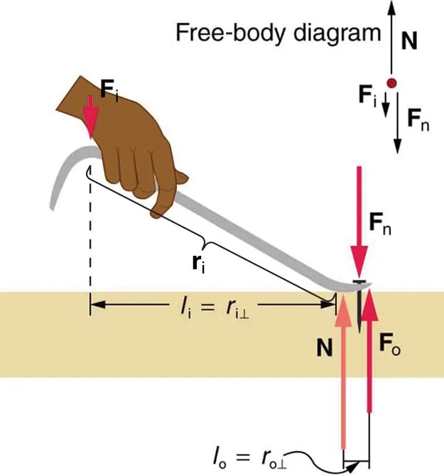
Figure 7.21 A nail puller is a lever with a large mechanical advantage. The external forces on the nail puller are represented by solid arrows. The force that the nail puller applies to the nail ([latex]\textbf{F}_{\text{o}}[/latex]) is not a force on the nail puller. The reaction force the nail exerts back on the puller ([latex]\textbf{F}_{\text{n}}[/latex]) is an external force and is equal and opposite to [latex]\textbf{F}_{\text{o}}[/latex]. The perpendicular lever arms of the input and output forces are [latex]l_{\text{i}}[/latex] and [latex]l_{o}[/latex]. Image from OpenStax College Physics 2e, CC-BY 4.0
Image Description
The image is a diagram illustrating the physics of a lever in use, labeled as a “free-body diagram.” It depicts a hand applying a downward force on one end of a crowbar, which is used as a lever. The descriptions and labels in the image are as follows:
- A hand holds the lever, applying a force labeled as Fi, represented by a downward arrow near the hand.
- The lever pivots on a point on a surface, with two arrows near the pivot point labeled Fn (downward) and N (upward). These represent the normal force and the ouput force, respectively.
- The force exerted by the lever on the surface is labeled Fo (upward arrow). It is opposing the downward force of Fn.
- The length from the hand to the pivot is labeled li = ri⊥.
- The length from the pivot to the point where the force Fo is applied is labeled lo = ro⊥.
- There is a smaller diagram in the top right corner that simplifies the forces into arrows, showing Fi and Fn acting downwards, N acting upwards.
Figure 7.21 shows a lever type that is used as a nail puller. Crowbars, seesaws, and other such levers are all analogous to this one. [latex]\textbf{F}_{\text{i}}[/latex] is the input force and [latex]\textbf{F}_{\text{o}}[/latex] is the output force. There are three vertical forces acting on the nail puller (the system of interest) – these are [latex]\textbf{F}_{\text{i}} , \textbf{F}_{\text{n}} ,[/latex] and [latex]\textbf{N}[/latex]. [latex]\textbf{F}_{\text{n}}[/latex] is the reaction force back on the system, equal and opposite to [latex]\textbf{F}_{\text{o}}[/latex]. (Note that [latex]\textbf{F}_{\text{o}}[/latex] is not a force on the system.)
[latex]\textbf{N}[/latex] is the normal force upon the lever, and its torque is zero since it is exerted at the pivot. The torques due to [latex]\textbf{F}_{\text{i}}[/latex] and [latex]\textbf{F}_{\text{n}}[/latex] must be equal to each other if the nail is not moving, to satisfy the second condition for equilibrium [latex]\left(\text{net } \tau = 0\right)[/latex]. (In order for the nail to actually move, the torque due to [latex]\textbf{F}_{\text{i}}[/latex] must be ever-so-slightly greater than torque due to [latex]\textbf{F}_{\text{n}}[/latex].) Hence,
[latex]l_{\text{i}} F_{\text{i}} = l_{\text{o}} F_{\text{o}}[/latex]
Notice that [latex]\textbf{r}_{\text{i}}[/latex] is the distance from the pivot point to the point where the input force [latex]\textbf{F}_{\text{i}}[/latex] is applied, and [latex]\textbf{r}_{\text{o}}[/latex] (not labeled on the diagram) is the distance from the pivot point to the point where the output force [latex]\textbf{F}_{\text{o}}[/latex] is applied. The distances [latex]l_{\text{i}}[/latex] and [latex]l_{\text{o}}[/latex] are the perpendicular components of the distances from where the input and output forces are applied to the pivot, as shown in the figure. Rearranging the last equation gives
[latex]\frac{F_{\text{o}}}{F_{\text{i}}} = \frac{l_{\text{i}}}{l_{\text{o}}} .[/latex]
What interests us most here is that the magnitude of the force exerted by the nail puller, [latex]F_{\text{o}}[/latex], is much greater than the magnitude of the input force applied to the puller at the other end, [latex]F_{\text{i}}[/latex]. For the nail puller,
[latex]\text{MA} = \frac{F_{\text{o}}}{F_{\text{i}}} = \frac{l_{\text{i}}}{l_{\text{o}}} .[/latex]
This equation is true for levers in general. For the nail puller, the MA is certainly greater than one. The longer the handle on the nail puller, the greater the force you can exert with it.
Two other types of levers that differ slightly from the nail puller are a wheelbarrow and a shovel, shown in Figure 9.22. All these lever types are similar in that only three forces are involved – the input force, the output force, and the force on the pivot – and thus their MAs are given by [latex]\text{MA} = \frac{F_{\text{o}}}{F_{\text{i}}}[/latex] and [latex]\text{MA} = \frac{d_{1}}{d_{2}}[/latex], with distances being measured relative to the physical pivot. The wheelbarrow and shovel differ from the nail puller because both the input and output forces are on the same side of the pivot.
In the case of the wheelbarrow, the output force or load is between the pivot (the wheel’s axle) and the input or applied force. In the case of the shovel, the input force is between the pivot (at the end of the handle) and the load, but the input lever arm is shorter than the output lever arm. In this case, the MA is less than one.
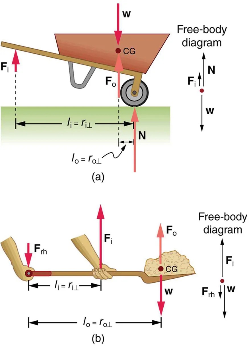
Figure 7.22 (a) In the case of the wheelbarrow, the output force or load is between the pivot and the input force. The pivot is the wheel’s axle. Here, the output force is greater than the input force. Thus, a wheelbarrow enables you to lift much heavier loads than you could with your body alone. (b) In the case of the shovel, the input force is between the pivot and the load, but the input lever arm is shorter than the output lever arm. The pivot is at the handle held by the right hand. Here, the output force (supporting the shovel’s load) is less than the input force (from the hand nearest the load), because the input is exerted closer to the pivot than is the output. Image from OpenStax College Physics 2e, CC-BY 4.0
Image Description
This image contains two diagrams, each illustrating a free-body diagram for different systems involving forces and torques.
Diagram (a):
- A wheelbarrow is shown with a labeled center of gravity (CG).
- The forces acting on it include the following:
- W: Weight of the load acting downward at CG.
- N: Normal force acting upward at the wheel.
- Fo: Force at the wheel.
- Fi: Input force applied upward by the person.
- Distances are labeled between forces:
- li = ri⊥: Distance from the input force to the pivot point (wheel).
- lo = ro⊥: Distance from the output force to the pivot point.
- A free-body diagram to the right shows arrows representing these forces, balancing around the wheel pivot.
Diagram (b):
- A shovel filled with a load is shown being held by two hands, with forces labeled:
- W: Weight of the load acting downward at CG.
- Fi: Input force applied upward by the person’s hands.
- Frh: Reaction force at the hand furthest from the load, acting downward.
- Fo: Force at the hand closest to the load, acting upward.
- Distances are labeled between forces:
- li = ri⊥: Distance from the input force to the nearest hand.
- lo = ro⊥: Total distance from the load to the reaction force.
- A free-body diagram to the right shows arrows representing these forces, balancing around the pivot point at the hand.
Example 7.3
What is the Advantage for the Wheelbarrow?
In the wheelbarrow of Figure 7.22, the load has a perpendicular lever arm of 7.50 cm, while the hands have a perpendicular lever arm of 1.02 m. (a) What upward force must you exert to support the wheelbarrow and its load if their combined mass is 45.0 kg? (b) What force does the wheelbarrow exert on the ground?
Strategy
Here, we use the concept of mechanical advantage.
Solution
(a) In this case, [latex]\frac{F_{\text{o}}}{F_{\text{i}}} = \frac{l_{i}}{l_{o}}[/latex] becomes
[latex]F_{\text{i}} = F_{\text{o}} \frac{l_{o}}{l_{i}} .[/latex]
Adding values into this equation yields
[latex]F_{\text{i}} = \left(\text{45}.\text{0} \text{ kg}\right) \left(9.80 \text{ m}/\text{s}^{2}\right) \frac{\text{0}.\text{075 m}}{\text{1}.\text{02 m}} = \text{32}.\text{4 N} .[/latex]
The free-body diagram (see Figure 7.22) gives the following normal force: [latex]F_{i} + N = W[/latex]. Therefore,
[latex]N = \left(\right. \text{45}.\text{0 kg} \left.\right) \left(9.80 \text{ m}/\text{s}^{2}\right) - \text{32}.\text{4 N} = \text{409 N}[/latex]. [latex]N[/latex] is the normal force acting on the wheel; by Newton’s third law, the force the wheel exerts on the ground is [latex]\text{409 N}[/latex].
Discussion
An even longer handle would reduce the force needed to lift the load. The MA here is [latex]\text{MA} = 1 . \text{02} / 0 . \text{0750} = \text{13} . 6[/latex].
Another very simple machine is the inclined plane. Pushing a cart up a plane is easier than lifting the same cart straight up to the top using a ladder, because the applied force is less. However, the work done in both cases (assuming the work done by friction is negligible) is the same. Inclined lanes or ramps were probably used during the construction of the Egyptian pyramids to move large blocks of stone to the top.
A crank is a lever that can be rotated [latex]\text{360}º[/latex] about its pivot, as shown in Figure 7.23. Such a machine may not look like a lever, but the physics of its actions remain the same. The MA for a crank is simply the ratio of the radii [latex]r_{\text{i}} / r_{0}[/latex]. Wheels and gears have this simple expression for their MAs too. The MA can be greater than 1, as it is for the crank, or less than 1, as it is for the simplified car axle driving the wheels, as shown. If the axle’s radius is [latex]2.0 cm[/latex] and the wheel’s radius is [latex]\text{24}.\text{0 cm}[/latex], then [latex]\text{MA} = 2.0 / \text{24}.\text{0} = 0 . \text{083}[/latex] and the axle would have to exert a force of [latex]\text{12},\text{000 N}[/latex] on the wheel to enable it to exert a force of [latex]\text{1000 N}[/latex] on the ground.
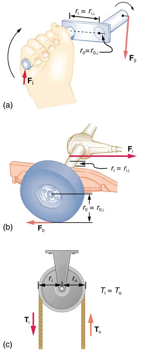
Figure 7.23 (a) A crank is a type of lever that can be rotated [latex]\text{360}º\text{ }[/latex] about its pivot. Cranks are usually designed to have a large MA. (b) A simplified automobile axle drives a wheel, which has a much larger diameter than the axle. The MA is less than 1. (c) An ordinary pulley is used to lift a heavy load. The pulley changes the direction of the force [latex]T[/latex] exerted by the cord without changing its magnitude. Hence, this machine has an MA of 1. Image from OpenStax College Physics 2e, CC-BY 4.0
Image Description
The image consists of three diagrams labeled as (a), (b), and (c), illustrating different mechanical systems involving forces and radii:
(a) A hand gripping a wrench, depicted as applying an input force (Fi) upwards on a bolt. The wrench applies an output force (Fo) downwards. The diagram highlights two radii: ri for the input and ro for the output.
(b) A car wheel attached to a rear axle. An input force (Fi) is directed rightward along the axle. An output force (Fo) acts leftward on the wheel. Radii ri and ro are indicated, with ri corresponding to the axle and ro to the wheel.
(c) A pulley system with two ropes. The input tension (Ti) acts on one side of the pulley, and the output tension (To) acts on the opposite side. The radii, ri and ro, are marked. The tensions are shown with downward and upward arrows, respectively, and it states “Ti = To“.
An ordinary pulley has an MA of 1; it only changes the direction of the force and not its magnitude. Combinations of pulleys, such as those illustrated in Figure 9.24, are used to multiply force. If the pulleys are friction-free, then the force output is approximately an integral multiple of the tension in the cable. The number of cables pulling directly upward on the system of interest, as illustrated in the figures given below, is approximately the MA of the pulley system. Since each attachment applies an external force in approximately the same direction as the others, they add, producing a total force that is nearly an integral multiple of the input force [latex]T[/latex].
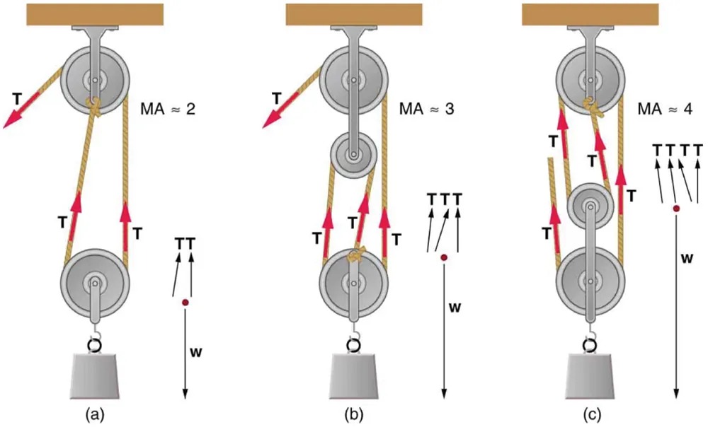
Figure 7.24 (a) The combination of pulleys is used to multiply force. The force is an integral multiple of tension if the pulleys are frictionless. This pulley system has two cables attached to its load, thus applying a force of approximately [latex]\text{2} T[/latex]. This machine has [latex]\text{MA} \approx 2[/latex]. (b) Three pulleys are used to lift a load in such a way that the mechanical advantage is about 3. Effectively, there are three cables attached to the load. (c) This pulley system applies a force of [latex]\text{4} T[/latex], so that it has [latex]\text{MA} \approx 4[/latex]. Effectively, four cables are pulling on the system of interest. Image from OpenStax College Physics 2e, CC-BY 4.0
Image Description
The image shows a series of diagrams illustrating three different pulley systems, each demonstrating varying mechanical advantages (MA). Each diagram highlights the forces involved and how they interact with the pulleys.
1. Diagram (a):
– Shows a pulley system with a mechanical advantage of approximately 2.
– Consists of two pulleys and a rope.
– The rope passes over both pulleys with three sections labeled “T” pointing in opposite directions, indicating tension forces.
– A weight labeled “w” is attached at the bottom of the rope.
2. Diagram (b):
– Shows a pulley system with a mechanical advantage of approximately 3.
– Consists of three pulleys and a rope.
– The rope wraps around the pulleys with four sections labeled “T”, depicting the tension forces working in the system.
– The weight “w” hangs from the bottom.
3. Diagram (c):
– Shows a pulley system with a mechanical advantage of approximately 4.
– Includes four pulleys and a rope.
– The rope creates five sections labeled “T”, illustrating the distributed tension forces in use.
– A weight “w” is suspended at the bottom of the setup.
Each diagram is visually distinct with forces clearly marked by arrows, showing how different configurations distribute tension to provide mechanical advantage.
