7.1 The First Condition for Equilibrium
Learning Objectives
By the end of this section, you will be able to:
- State the first condition of equilibrium.
- Explain static equilibrium.
- Explain dynamic equilibrium.
The first condition necessary to achieve equilibrium is the one already mentioned: the net external force on the system must be zero. Expressed as an equation, this is simply
[latex]\text{net} \mathbf{F} = 0[/latex]
Note that if net [latex]\mathbf{F}[/latex] is zero, then the net external force in any direction is zero. For example, the net external forces along the typical x– and y-axes are zero. This is written as
[latex]\text{net } F_{x} = 0 \text{and net} F_{y} = 0[/latex]
Figure 7.2 and Figure 7.3 illustrate situations where [latex]\text{net} \mathbf{F} = 0[/latex] for both static equilibrium (motionless), and dynamic equilibrium (constant velocity).
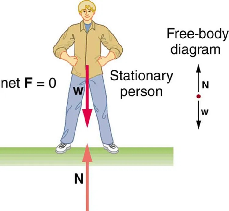
Figure 7.2 This motionless person is in static equilibrium. The forces acting on him add up to zero. Both forces are vertical in this case. Image from OpenStax College Physics 2e, CC-BY 4.0
Image Description
The image is a diagram depicting a stationary person standing upright on a surface. The person is shown with their arms akimbo, wearing a beige shirt and blue pants. There are arrows and labels indicating forces acting on the person, emphasizing the concept of equilibrium.
– A vertical arrow labeled “w” points downward, representing the weight force acting on the person.
– Another arrow, labeled “N,” points upward from the surface, representing the normal force exerted by the ground on the person.
– The labels “net F = 0” and “Stationary person” indicate that the net force on the person is zero, meaning they are in equilibrium and not accelerating.
To the right of the person, there is a simplified free-body diagram showing:
– A small red dot with an upward arrow labeled “N” and a downward arrow labeled “w,” visually demonstrating the forces acting on the person and reinforcing that these forces are balanced.
The setting conveys basic physics concepts of force, equilibrium, and free-body diagrams.
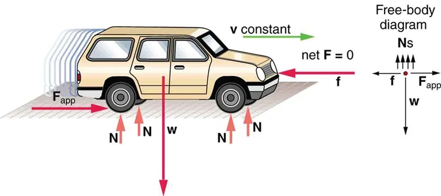
Figure 7.3 This car is in dynamic equilibrium because it is moving at constant velocity. There are horizontal and vertical forces, but the net external force in any direction is zero. The applied force [latex]\mathbf{F}_{\text{app}}[/latex] between the tires and the road is balanced by air friction, and the weight of the car is supported by the normal forces, here shown to be equal for all four tires. Image from OpenStax College Physics 2e, CC-BY 4.0
Image Description
The image shows a side view of a car on a flat surface, illustrating various forces acting on it.
– Car Description: The car is beige with four doors and is oriented to the right. It is on a slightly textured surface.
– Forces on the Car:
– Fapp (Applied Force): A horizontal red arrow pointing to the right, starting from the car’s rear.
– f (Friction Force): A horizontal red arrow pointing to the left, at the front of the car.
– w (Weight): A vertical red arrow pointing downward from the car’s center.
– N (Normal Force): Four vertical red arrows pointing upward beneath the car’s tires, balancing the weight.
– Velocity Indicator: A green arrow labeled “v constant” indicating constant velocity, pointing to the right in front of the car.
– Free-Body Diagram:
– Shown on the right side of the image.
– Consists of a dot representing the car, with arrows indicating forces:
– Ns (Normal Force): Multiple upward arrows.
– f (Friction Force): A leftward arrow.
– Fapp (Applied Force): A rightward arrow.
– w (Weight): A downward arrow.
– Additional Notes:
– The text “net F = 0” is next to the free-body diagram, indicating that the net force acting on the car is zero, resulting in a balanced state.
However, it is not sufficient for the net external force of a system to be zero for a system to be in equilibrium. Consider the two situations illustrated in Figure 7.4 and Figure 7.5 where forces are applied to an ice hockey stick lying flat on ice. The net external force is zero in both situations shown in the figure; but in one case, equilibrium is achieved, whereas in the other, it is not. In Figure 7.4, the ice hockey stick remains motionless. But in Figure 7.5, with the same forces applied in different places, the stick experiences accelerated rotation. Therefore, we know that the point at which a force is applied is another factor in determining whether or not equilibrium is achieved. This will be explored further in the next section.
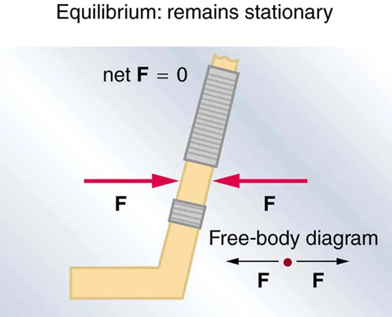
Figure 7.4 An ice hockey stick lying flat on ice with two equal and opposite horizontal forces applied to it. Friction is negligible, and the gravitational force is balanced by the support of the ice (a normal force). Thus, [latex]\text{net} \mathbf{F} = 0[/latex]. Equilibrium is achieved, which is static equilibrium in this case. Image from OpenStax College Physics 2e, CC-BY 4.0
Image Description
The image illustrates a concept called equilibrium in physics using a free-body diagram. The setup includes a beige-colored object that is bent at a right angle, with two springs wrapped around it. The springs demonstrate forces acting in opposite directions.
– Two red arrows, labeled “F,” point towards the center from opposite directions, indicating equal forces.
– A text at the top states “Equilibrium: remains stationary,” explaining that the net force is zero.
– “Net F = 0” is written above the object.
– Below the object, a small free-body diagram shows a dot with two arrows pointing left and right, both labeled “F,” corroborating that the forces are balanced.
The object remains stationary as the forces cancel each other out, illustrating equilibrium.
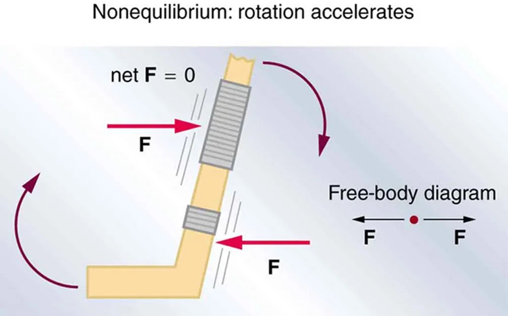
Figure 7.5 The same forces are applied at other points and the stick rotates—in fact, it experiences an accelerated rotation. Here [latex]\text{net} \mathbf{F} = 0[/latex] but the system is not at equilibrium. Hence, the [latex]\text{net} \mathbf{F} = 0[/latex] is a necessary—but not sufficient—condition for achieving equilibrium. Image from OpenStax College Physics 2e, CC-BY 4.0
Image Description
This image is a physics diagram titled “Nonequilibrium: rotation accelerates”. It illustrates a scenario with forces acting on an object. The object is depicted as a bent rod. Two forces labeled F are applied horizontally in opposite directions, one at the top and another near the bottom of the rod. These forces are equal, creating a condition where the net force (net F = 0) is zero.
Despite the net force being zero, the object is shown experiencing rotational acceleration, indicated by curved arrows. The top and bottom of the rod are depicted with rotational arrows arching in opposite directions around the midsection of the rod, which suggests they are causing the rod to rotate.
To the right of the rod, a “Free-body diagram” is drawn, showing a single point with horizontal forces labeled F acting in opposite directions. This emphasizes that no linear acceleration occurs, only rotational acceleration.
PhET Explorations
Torque
Investigate how torque causes an object to rotate. Discover the relationships between angular acceleration, moment of inertia, angular momentum and torque.
