6.3
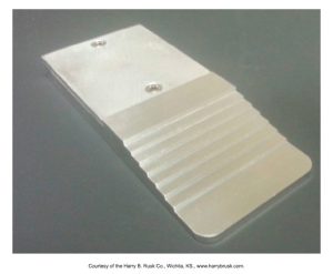
A stepwedge is made of uniform-layered thicknesses of aluminum. A stepwedge can demonstrate short-scale and long-scale contrast. The stepwedge consists of uniform layered thicknesses of an x-ray absorbing material where different densities appear on the dental radiograph. The stepwedge is used to demonstrate corresponding film densities and contrast scales.
Here is an image of what a stepwedge looks like.
 |
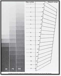 |
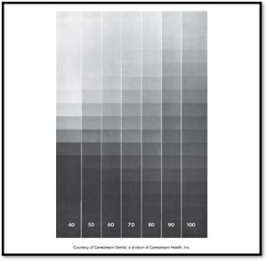
| Seven radiographs of a stepwedge made at 40 to 100 kV are shown side by side. As the kV was increased, the mA was reduced to maintain a roughly uniform middle-step density.
Note: the long grayscale (low contrast) image with high kV and the short gray scale (high contrast) image when using low kV. |
Radiographs taken at 40 kVp are predominantly black and white; that is, they have high contrast (a short-contrast scale). Those taken at 100 kVp show many shades of gray (a long-contrast scale). |
Geometric Characteristics
The three geometric characteristics of a dental radiograph are sharpness, magnification, and distortion.
Sharpness
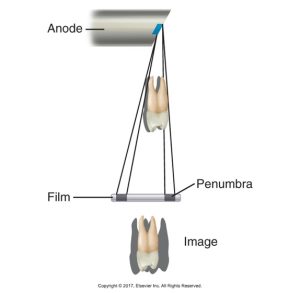
Sharpness is the capability of the x-ray receptor to reproduce the distinct outlines of an object. A certain lack of image sharpness is present in every radiograph; it is called the penumbra. Penumbra is the fuzzy or blurred area that surrounds an image. A lack of sharpness can change a diagnosis dramatically, and it may cause a problem to be undetected at an early stage when the prognosis would have been more favorable.
Sharpness is influenced by three factors which are:
- Focal spot size – the smaller the focal spot, the sharper the image appears
- Film composition – not a factor with digital imaging
- Movement – causes a loss of image sharpness
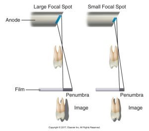
For the focal spot and penumbra, the smaller the focal spot area, the sharper the image appears; the larger the focal spot area, the greater the amount of penumbra and the greater the loss of image sharpness. The size of the focal spot ranges from .6mm to 1mm, according to the manufacturer.
The diagram below shows the comparison of dental x-ray images. It is showing the effect of large and small focal spots on image sharpness and the extent of the penumbra, or blurred edges, around the tooth representation.
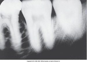
For motion and penumbra, the diagram below illustrates the influence of motion on image sharpness. Note that the image outline is blurred because of the penumbra formation.
Movement and blurred images can occur in a radiograph when a patient moves during an x-ray exposure. In the image below, note the blurred image outline.
Magnification
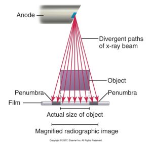
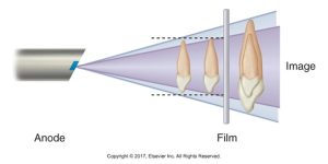
Magnification results from the divergent paths of the x-ray beam as they radiate from the focal spot. Magnification is especially important when measuring the length of a tooth during root canal therapy.
Influencing factors of magnification are:
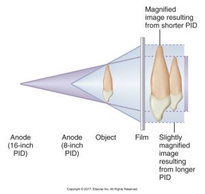
- Target-receptor distance – a longer PID and target-receptor distance result in less image magnification
- Object-receptor distance – an increase in object-receptor distance results in an increase in image magnification
The diagram below illustrates magnification as a result of the divergent paths of the x-ray beam.
For target-receptor distance, a longer position-indicating device (PID) (16 inches) and target-receptor distance results in less image magnification. The diagram below is of a dental x-ray imaging showing the difference in image magnification with an 8-inch and a 16-inch Position Indicating Device (PID).
For object-receptor distance, the closer the tooth is to the receptor, the less enlargement is seen in the image. The diagram below shows the cone of radiation from an x-ray anode to film, with two teeth depicted at different distances from the film, resulting in different image sizes.
Distortion
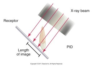
Distortion is a variation in the true size and shape of the object being radiographed. Results from an unequal magnification of different parts of the same object are because of improper receptor alignment or angulation of the x-ray beam. Distortion occurs when a radiograph is taken at a vertical angle that is greater than or less than necessary, resulting in an image that appears either stretched out or shorter than it really is.
Influencing factors for distortion are:
- Object-receptor alignment – the object and receptor must be parallel to each other or there will be distortion
- X-ray beam angulation – the x-ray beam must be directed perpendicular to the tooth and receptor
For a distorted image, if the tooth and the receptor are not parallel, an angular relationship is formed, and a distorted image results. In the example below, the length of the tooth that appears in the image is shorter than the actual tooth.
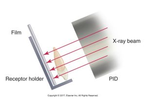
To limit distortion, the central ray of the x-ray beam must be perpendicular to the tooth and the receptor. The diagram below is of an x-ray setup with a film in a receptor holder and a tooth, showing the X-ray beam from a PID producing a non-distorted image on the film.
You have completed all of the Module 1 chapters. Please return to Blackboard to complete the Chapter Case Study Quizzes.
Media Attributions
- Iannucci & Howerton: Dental Radiography Principles and Techniques, 6th Edition, Chapter 6, CC BY-NC-ND
