4.1
Patient Protection
X-radiation causes biological changes in living cells; it adversely affects all living tissues. Our goal is to minimize the amount of radiation received by the patient and maximize the benefits. Techniques may be used before, during, and after the procedure to protect the patient.
Before Exposure
Before exposure, prescribing dental radiographs and the proper equipment is mandatory.
| Test or Procedure | Frequency |
| 1. Photographic quality control | Every operational day |
| 2. Patient entrance exposure measurements | Every twelve months and upon alteration or servicing of the machine |
| 3. Collimation | Every twelve months and upon alteration of servicing of the machine |
| 4. Half-value layer | Every twelve months and upon alteration or servicing of the machine |
Tests or Procedure: Table 3 Dental Facility R.R.O. 1990, Reg.543
Prescribing Dental Radiographs
Professional judgment is used to determine the number, type, and frequency of dental radiographs. The Food & Drug Administration (FDA) has published guidelines. Every patient should be evaluated on an individual basis to determine what x-rays are necessary. Proper prescribing of dental x-rays can minimize the amount of radiation exposure. Only a licensed dentist is allowed to prescribe dental radiographs in a dental office.
Proper Equipment
The use of equipment that complies with state/provincial and federal radiation guidelines will minimize the radiation a patient receives, which are:
- Inherent filtration
- Filtration
- Added filtration
- Total filtration
- Collimation
- Position-indicating device
And the x-ray tubehead should be properly equipped with aluminum filters, a lead collimator, and Position Indicating Device (PID).
Inherent Filtration
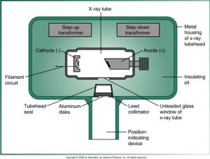
Inherent filtration occurs when the primary beam passes through the X-ray tube’s glass window of the x-ray tube, the insulating oil, and the tubehead seal. It is equivalent to approximately 0.5 to 1.0 mm. of aluminum. and inherent filtration alone does not meet the standards regulated by state and federal law, so additional filtration is required. Filtration is necessary to absorb the low-energy x-ray photons emitted by the tube before they hit their target.
Filtration
Inherent filtration takes place when the primary beam passes through the glass window of x-ray tube, the insulating oil, and the tubehead seal. Added filtration refers to the aluminum discs placed between the collimator and the tubehead seal.
Below is a diagram of an x-ray tube structure with its components, including the cathode, anode, transformers, and various parts of the tube head assembly.
Added Filtration
An aluminum disk is placed between the collimator and the tubehead seal to filter out longer wavelength, lower energy x-rays from the x-ray beam. The filtration results in a higher-energy and more penetrating useful beam.
Total Filtration
Collimation
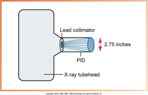
Collimation restricts the size and shape of the x-ray beam and it reduces patient exposure. Collimator round produces a cone-shaped beam 2.75 inches in diameter, and rectangular produces a rectangular beam slightly larger than a #2 film.
The hole in the collimator may be either round or rectangular in shape. The safety code 30: the primary radiation beam must be collimated in size at the end of the applicator (PID) to a circle not more than 7 centimeters in diameter or a rectangle of area not more than 38.5 cm2.
Below is an image of two parts of a radiology device, with one part showing a circular opening and the other displaying a metallic component with a rectangular aperture, part of an X-ray collimator system.
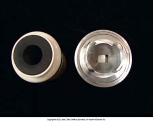
Federal regulations require that the diameter of a collimated x-ray beam be restricted to 7 cm or 2.75 inches at the patient’s skin. PID, position-indicating device.
Below is a diagram showing an x-ray tubehead with a lead collimator and a position-indicating device (PID), highlighting the 2.75 inches diameter of the collimated X-ray beam.
Position-Indicating Device
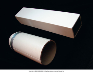
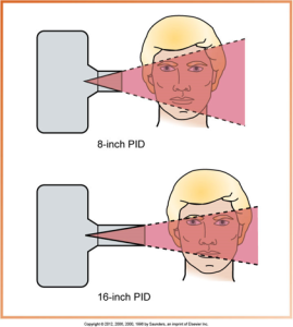
An extension of the x-ray tubehead is used to direct the x-ray beam. It may be conical, rectangular, or round. Conical PIDs are no longer used in dentistry; they scatter radiation, and rectangular and round PIDs usually come in 8- or 16-inch lengths. They are open-ended and lead-lined. The long PID produces the least divergence of the x-ray beam.
Below is a diagram comparing two types of position-indicating devices (PIDs) for dental x-rays: a pointed plastic PID with scattered radiation on the left and an open-ended PID with directed radiation on the right.
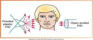
A plastic, pointed position-indicating device (PID) produces scatter radiation and is no longer used in dentistry. Safety code 30: a position-indicating device must be provided to limit the minimum focal spot-to-skin distance to not less than 18 centimeters (7 ¼ inches). The applicator must be an open-ended type. Pointed cones or close-ended applicators must not be used.
Open-ended, lead-lined round and rectangular position-indicating devices (PIDs). Here is an image of two position-indicating devices (PIDs) for radiology, one cylindrical and one rectangular, both open-ended and lead-lined.
Compared with a short (8-inch) position-indicating device (PID), the longer (16-inch) PID is preferred because it produces less divergence of the x-ray beam.
The diagram below compares the beam spread from an 8-inch PID to a 16-inch PID in dental X-ray imaging, showing a more focused beam with a longer PID.
Media Attributions
- Iannucci & Howerton: Dental Radiography Principles and Techniques, 6th Edition, Chapter 4, CC BY-NC-ND

