25.1
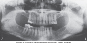
A panoramic image in dental shows a wide view of the upper and lower jaws. Panoramic imaging is used to examine the upper and lower jaws on a single projection, is an extraoral technique, and bite-wings and pas are often used to supplement a panoramic image to detect dental caries or periapical lesions.
An overall image of the maxilla and mandible is captured and is often used to supplement bite-wing and selected periapical images. Images seen on a panoramic projection are not as defined or sharp as the images seen on intraoral projections.
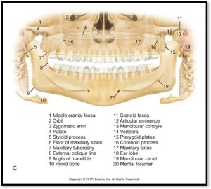
Here are some images displaying what a panoramic image looks like and the panoramic anatomy.
 |
 |
Fundamentals
In panoramic imaging, the receptor and x-ray tubehead move around the patient. The x-ray tube rotates around the patient’s head in one direction while the receptor rotates in the opposite direction, and the patient may stand or sit in a stationary position, as shown in the diagram below.
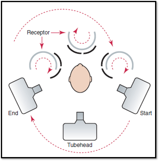
The movement of the receptor and the tubehead produces an image through the process known as tomography. Tomography is an imaging technique that allows the imaging of one layer or section of the body while blurring images from structures in other planes.
Rotation Center
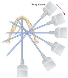
The pivotal point, or axis, around which the cassette carrier and x-ray tubehead rotate is the rotational center. Modern panoramic x-ray units use a continuously moving center of rotation rather than multiple fixed center locations.
The diagram below highlights the concept of a focal point where all x-ray beams converge.
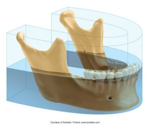
Focal Trough
A focal trough can be defined as a three-dimensional curved zone in which structures are demonstrated on a panoramic image. A theoretical concept used to determine where the dental arches must be positioned to obtain the sharpest image.
The graphic below illustrates the focal trough areas used in panoramic dental imaging. This visual demonstrates the specific regions of interest captured during the scan.
Resultant Images
- A real image results when a structure lies between the receptor and the moving rotation center.
- A double image results when an anatomic structure that is located behind the moving rotation center is penetrated twice by the x-ray beam.
- A ghost image results when an anatomic structure or object is located outside of the focal plane and close to the x-ray source.
Equipment
Equipment involved in panoramic imaging includes panoramic x-ray units, image receptors, and other additional equipment.
Panoramic X-Ray Units
There are a number of different panoramic x-ray units and they all have similar components.
A x-ray tubehead is similar to an intraoral x-ray tubehead, and a collimator differs from the collimator used in the intraoral x-ray tube head. The collimator used in the panoramic x-ray machine is a lead plate with an opening in the shape of a narrow vertical slit.
An x-ray beam emerges from the panoramic tubehead through the collimator as a narrow band. It passes through the patient and exposes the receptor through another vertical slit in the cassette carrier. The vertical angulation is fixed so that the x-ray beam is directed slightly upward.
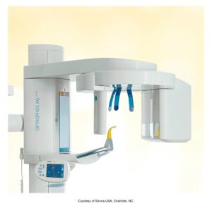
Here is an image of an advanced panoramic dental x-ray unit. The machine is designed for comprehensive dental diagnostics with an emphasis on ease of use and precise imaging.
Head Positioner
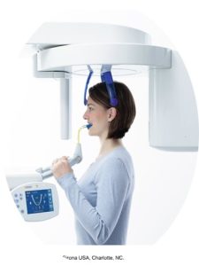
A head positioner consists of a chin rest, notched bite-block, forehead rest, and lateral head supports or guides. It is used to align the patient’s teeth as accurately as possible. Here is an image of what a head positioner in a panoramic x-ray unit looks like.
Exposure Factors
The suggested exposure factors for milliamperage and kilovoltage are provided by the manufacturer and can be varied to accommodate patients of different sizes. Exposure time can be adjusted based on the type of image obtained. Below is an image of a control panel on a dental x-ray machine.

Image Receptors
In panoramic x-ray units, the image receptor may be a direct digital sensor, a PSP plate, or film. The image must clearly indicate the patient’s right and/or left sides, regardless of the receptor type.
Cassette
A cassette is a device used to hold the extraoral film (with a PSP sensor). It may be rigid or flexible, curved or straight. It must be light-tight and marked to orient the finished image.
Step-by-Step Procedures
The step-by-step procedure includes:
- Equipment preparation
- Patient preparation
- Patient positioning
Watch this video to learn about panoramic exposure with patient positioning:
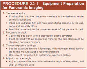
Equipment Preparation
The table below displays the 4 steps for the equipment preparation for panoramic imaging.
Patient Preparation
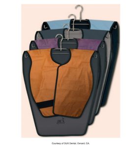
When preparing the patient for panoramic imaging, explain the imaging procedures to them, place a lead apron without a thyroid collar on the patient, and secure it. A double-sided lead apron is recommended. Then, remove all objects from the head and neck area that may interfere with the procedure. The image below shows three dental lead aprons used for patient protection during x-ray procedures.
Patient Positioning
When focusing on the patient positioning, you want to instruct the patient to sit or stand “as tall as possible” with the back straight and erect. Then, instruct the patient to bite on the plastic bite-block and position the midsagittal plane perpendicular to the floor.
 |
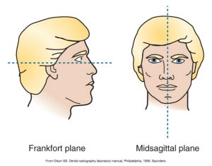 |
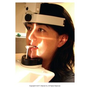
| A woman positioned using a bite block and wearing a head-mounted device designed to stabilize her head during the imaging process. | The diagram shows the anatomical planes used in dental imaging: the Frankfort plane, indicated by a horizontal line through the profile view, and the midsagittal plane, marked by a vertical line through the front view of a face. These reference lines are critical for proper patient positioning in radiographic procedures. |
Next, position the Frankfort plane parallel to the floor, instruct the patient to position the tongue on the roof of the mouth, and keep the tongue in that position during exposure to the receptor. Then, have the patient close their lips around the bite-block and ask them to remain still while the machine rotates during exposure. Expose the receptor and proceed with receptor processing.
 |
 |
| A close-up photo of a woman wearing a head-mounted stabilizer and biting down on a bite block to ensure accurate positioning and alignment during the imaging process. | A side profile of a woman wearing a head-mounted stabilizer and biting on a bite block, which helps in maintaining the correct position during the dental imaging process. The lighting emphasizes the precise setup needed for accurate diagnostics.
|
Media Attributions
- Iannuci: Dental Radiography, 6th Edition, Chapter 25, CC BY-NC-ND
