22.1
Receptor Exposure Errors
Receptor exposure errors that result in nondiagnostic images include:
- Unexposed receptors
- Overexposed receptors
- Underexposed receptors
All of these errors produce images that are too light or too dark. A radiographer must be able to recognize exposure errors, identify causes, and know the necessary steps to correct such problems.
Unexposed Receptor
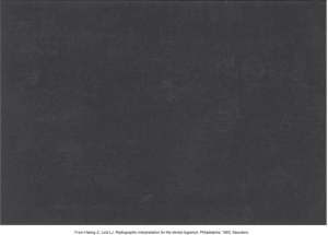
For unexposed receptors, the receptor may occur with digital sensors or film, and the image’s appearance appears clear. The cause of this is the failure to turn on the x-ray machine, electrical failure, and malfunction of the x-ray machine. The correct way is to ensure the x-ray machine is turned on and listen for the audible exposure signal.
The image below shows an unexposed receptor that appears clear.

Film Exposed to Light
When film is exposed to light, the receptor occurs only with film, and the image appears black. The cause of this is the film was exposed to white light. To correct this, do not unwrap in a room with white light, check the darkroom for light leaks, and turn off all lights in the darkroom except the safelight.
The image below shows a film that was exposed to light that appears black.
Overexposed Receptor
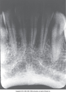
For overexposed receptors, the receptor may occur with digital sensors or film, and the image may appear dark or high in density. The cause of this is because of excessive exposure time, kilovoltage, and milliamperage. To correct this, check the settings and reduce as needed before exposing receptor.
Below is an image of an overexposed receptor that appears dark.
Underexposed Receptor
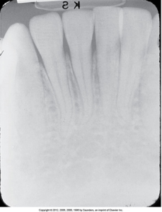
For underexposed receptors, the receptor may occur with digital sensors or film, and the image appears light or low in density. This is caused by the receptor being underexposed. To correct this, check the exposure time, kilovoltage, and milliamperage settings on the x-ray machine before exposing the receptor.
Below is an image of an underexposed receptor that appears light.
Periapical Technique Errors
Periapical technique errors include problems with receptor placement, angulation, and beam alignment. A dental radiographer must be able to recognize periapical technique errors, identify their causes, and know the necessary steps to correct such problems.
Receptor placement problems can be caused by incorrect receptor placement that is absence of apical structures or a dropped film corner. Angulation problems are incorrect horizontal angulation and incorrect vertical angulation. PID alignment problems are cone-cut with a beam alignment device and cone-cut without a beam alignment device.
Receptor Placement Problems
Each periapical receptor must be positioned in a certain way to show specific teeth and related anatomic structures. The edge of the periapical receptor must be placed parallel to the incisal or occlusal surfaces of the teeth and extend ⅛ inch beyond the incisal or occlusal surfaces. A non-diagnostic image may result from improper placement of a receptor over the area of interest, inadequate coverage of the apical regions, or a dropped receptor corner.
Absence of Apical Structures
The absence of apical structure errors occurs with both the paralleling and bisecting techniques. The receptor may occur with digital sensors or film, and no apices will appear on the receptor. The cause of this is the receptor was not positioned in the patient’s mouth to cover the apical regions of the teeth. To correct this error, make certain no more than ⅛ inch of the receptor edge extends beyond the incisal-occlusal surfaces of the teeth.
Dropped Receptor Corner
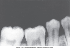
Dropped receptor corner errors occur when the finger-holding method is used with the bisecting technique. The receptor may occur with digital sensors or film, and the occlusal plane may appear tipped or tilted. The receptor’s edge was not parallel to the incisal-occlusal surfaces of the teeth, which is the cause of this. to correct this error, make certain the edge of the receptor is placed parallel to the incisal-occlusal surfaces of the teeth.
 |
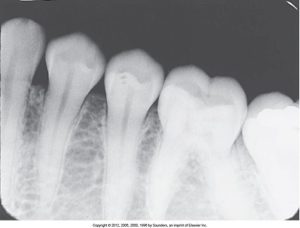 |
| This is an image of improper placement and missing apical structures. | This is an image of improper placement with a dropped corner, which is seen when the edge of the receptor is not placed parallel to the incisal or occlusal surfaces of teeth. |
Angulation Problems
Angulation is a term used to describe the alignment of the central ray of the x-ray beam in the horizontal and vertical planes. This can be varied by moving the PID in either a horizontal or vertical direction. Horizontal angulation refers to the positioning of the PID in a horizontal, side-to-side plane, and vertical angulation refers to the positioning of the PID in a vertical, up-and-down plane. Incorrect vertical angulation results in an image that is not the same length as that of the tooth; the image appears shorter or longer instead.
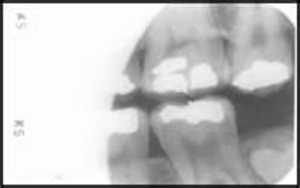
Below is an image of incorrect horizontal angulation results in overlapped contact areas.
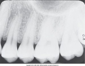
Overlapped Contacts: Incorrect Horizontal Angulation
For incorrect horizontal angulation, the receptor may occur with digital sensors or film, and paralleling or bisecting techniques may occur and appear as overlapped contacts. The proximal surfaces of adjacent teeth appear overlapped in the periapical exposure. This prevents the examination of interproximal areas. The central ray was not directed through interproximal spaces, which is the cause of incorrect horizontal angulation. To correct this, direct the x-ray beam through interproximal regions.
Foreshortened Images: Incorrect Vertical Angulation
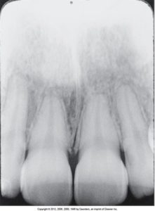
For incorrect vertical angulation, the receptors may occur with digital sensors or film, and bisecting technique may occur when beam alignment is not used. Images will appear as short teeth with blunted roots. This causes excessive vertical angulation; to correct it, do not use it with the bisecting technique.
If the vertical angulation is too steep, the image of the tooth on the receptor is shorter than the actual tooth; the images are foreshortened, as shown in the image below.
Elongated Images: Incorrect Vertical Angulation
Incorrect vertical angulation is the most common error. It is when the receptor may occur with digital sensors or film, and the bisecting technique may occur when a beam alignment device is not used. The image will appear as long, distorted teeth. Insufficient vertical angulation is the cause, and the correction for this is to use adequate vertical angulation with the bisecting technique.
If the vertical angulation is too flat, the image of the tooth on the receptor is longer than the actual tooth; the images are elongated, as shown in the image below.
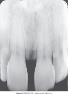
Position Indicating Device (PID) Alignment Problems
If the PID is misaligned and the x-ray beam is not centered over the receptor, a partial image results. A “cone-cut” image appears as a clear or white unexposed area on a dental image and may occur with a rectangular or round PID. If a round PID is used, the cone-cut appears with a curved border. The cone-cut appears with a linear border if a rectangular PID is used.
Cone-Cut with Beam Alignment Device
The receptors may occur with digital sensors or film for cone-cut with beam alignment devices. A paralleling or bisecting technique may occur when a beam alignment device is used. A clear area appears on the image. The cause is that the PID was not correctly aligned with the periapical beam alignment device; to correct it; the x-ray beam must be centered over the receptor and ensure the PID and the aiming ring are flush and aligned.
Cone-Cut without Beam Alignment Device
The receptors may occur with digital sensors or film for cone-cut without beam alignment devices. A bisecting technique may occur when a beam alignment device is not used, and a clear area appears on the image. This is caused by the PID not being directed at the receptor’s center, which can be corrected by ensuring the x-ray beam is centered over the receptor.
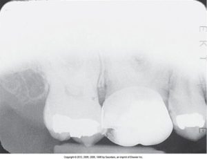 |
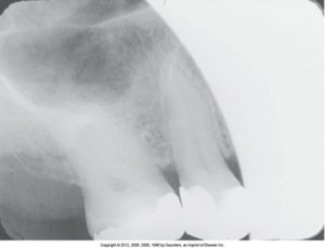 |
| This image shows a cone-cut when the position-indicating device (PID) is not properly aligned with the periapical beam alignment device. | This image shows a cone-cut as a curved, unexposed (clear) area on the radiograph. |
Media Attributions
- Iannuci: Dental Radiography, 6th Edition, Chapter 22, CC BY-NC-ND

