21.3
The rules of the bite-wing technique are as follows:
- Receptor placement
- Receptor position
- Vertical angulation
- Horizontal angulation
- Receptor exposure
Step-by-Step Procedures
The step-by-step procedures for the bite-wing technique are:
- Patient preparation
- Equipment preparation
- Exposure sequence for receptor placements
- Receptor placement
Patient Preparation
First, infection control procedures and preparation of the treatment area and supplies should be completed before seating the patient. You will then explain the imaging procedure to the patient, position them upright in the chair, and adjust the headrest. Then, go ahead and secure the lead apron with a thyroid collar. Then, the patient will be requested to remove eyeglasses and all objects from the mouth.
Equipment Preparation
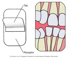
For equipment preparation, set the exposure factors. If a beam alignment device is used, open the sterilized receptor package containing the beam alignment device and assemble the device on a covered work area. If a bite-wing tab is used, attach the tab to the white side of the receptor (black side of the packet) on the correct side of the receptor.
Exposure Sequence for Receptor Placements
The exposure sequence for receptor placement is as follows:
- Two bite-wing receptors are typically exposed on each side of the arch.
- One bite-wing receptor may be sufficient when posterior teeth are missing.
- The number of bite-wings taken is dependent upon the curvature of the teeth and the number of teeth present in the posterior areas.
- In adult patients, four bite-wings are taken: one right premolar, one right molar, one left premolar, and one left molar using a digital receptor.
- Four size 2 films are taken for bite-wings in adult patients using traditional film radiography.
| For bite-wings and periapicals (CMRS/FMS) |
|
| Bite-wings only |
|
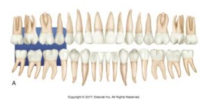
The Premolar Bite-Wing
 |
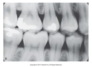 |
| A. Receptor placement | B. Resultant image |
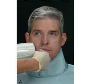
Correct Horizontal Angulation
 |
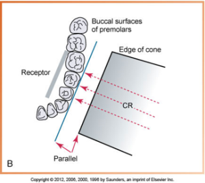 |
| A. To better visualize the curvature of the arch, place the index finger along the premolar area. | B. Correct horizontal angulation of the premolar area. |
The Premolar Bite-Wing
 |
 |
| A. Receptor placement | B. Resultant image |
 |
|
| The middle of the position-indicating device (PID) should be directed at the level of the occlusal plane.
In the Iannucci & Howerton, Dental Radiography Principles & Techniques, 6th Edition textbook, starting on page 221, refer to Helpful Hints: Premolar BW Placement is Easy as 1,2,3, and Premolar Checklist. |
|
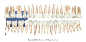
The Molar Bite-Wing
 |
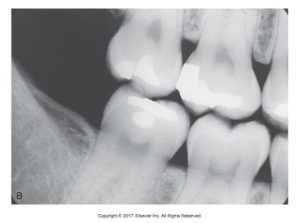 |
| A. Receptor placement | B. Resultant image |
Correct Horizontal Angulation
 |
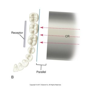 |
| A. To better visualize the curvature of the arch, place the index finger along the molar area. | B. Correct horizontal angulation of the molar area. |
 |
|
| The middle of the position-indicating device (PID) should be directed at the level of the occlusal plane. | |
Receptor Placement for Bite-Wing Images
Receptor placement is the specific area where the receptor must be positioned before exposure and is dictated by the teeth and surrounding structures. The placement is the right and left premolar exposures and the right and left molar exposures. The receptor is placed after the vertical and the horizontal angulations have been set.
In the posterior bite-wing series, the receptors are placed horizontally. The identification dot (or ‘a’) on a phosphor plate has no bearing on bite-wing images. The receptor must be centered over the area to be examined. Ask the patient to “slowly bite” on the bite-wing tab or bite-block of the beam alignment device.
Posterior Receptor Placement
Placement for a four-receptor posterior bite-wing series includes:
- Right and left premolar exposures
- Rights and left molar exposures
In the Iannucci & Howerton, Dental Radiography Principles & Techniques, 6th Edition textbook, starting on page 221, refer to Helpful Hints: Molar Bite Wing is as easy as 1, 2, 3 and Procedure 21-4 Molar BW Exposure with Bite Tab (Figures 21-16 to 21-25).
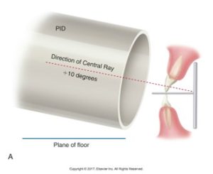
Vertical Bite-Wings
Verticle bite-wings are used to examine the level of alveolar bone. They are placed with the long portion of the receptor in a vertical direction and are often used as post-treatment or follow-up films for patients with bone loss caused by periodontal disease.
Modified CMS may be prescribed using vertical bite-wing images. Seven receptors are used to cover canine, midline, premolar, and molar areas.
Three anterior and four posterior include size 2 receptors used for all exposures or a combination of size 1 (anterior) and size 2 (posterior).
 |
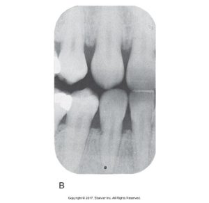 |
| A. Center the receptor vertically at midline, and stabilize the patient by having him or her gently close on the tab at the incisal edges of teeth. Teeth meet the tab in the end-to-end position. Suggested vertical angulation is + 10 degrees toward the center of the receptor; horizontally, the x-ray beam is directed through the interproximal spaces. | B. Bite-wing image of the right canine area. |
Below is a diagram displaying a dental bite-wing tab and receptor placement for capturing an image of multiple teeth.
Modifications in Bite-Wing Technique
Edentulous spaces are when a cotton roll must be placed in the area of the missing tooth to support the bite-wing tab or beam alignment device and bony growths are when the receptor must be placed between the tori and the tongue.
Here is an image of a hexagonal bite-block used for holding dental x-ray film or digital sensors in place during imaging procedures.

Media Attributions
- Iannuci: Dental Radiography, 6th Edition, Chapter 21, CC BY-NC-ND

