20.1
The bisecting technique is another method that can be used to expose periapical images.
An understanding of these basic terms is necessary before learning the bisecting technique.
Term |
Definition |
| Angle | In geometry, a figure formed by two lines diverging from a common point. |
| Bisect | To divide into two equal parts. |
| Triangle | In geometry, a figure formed by connecting three points not in a straight line by three straight-line segments; the figure has three angles. |
| Triangle, Equilateral | In geometry, a triangle with three equal sides. |
| Triangle, Right | In geometry, a triangle with one 90-degree angle (right angle). |
| Triangles, Congruent | In geometry, triangles that are identical and correspond exactly when superimposed. |
| Hypotenuse | In geometry, the side of a right triangle opposite the right angle. |
| Isometry | Equality of measurement. |
| Long Axis of the tooth | An imaginary line that divides a tooth longitudinally into two equal halves. |
| Central Ray | The central portion of the primary beam of x-radiation, abbreviated CR. |
The diagram below displays the different angles of a triangle.

Principles of Bisecting Technique
The rule of isometry is that two triangles are equal if they have two equal angles and share a common side. This geometric principle is applied to the bisecting technique in dental imaging to form two imaginary equal triangles.
Rule of Isometry
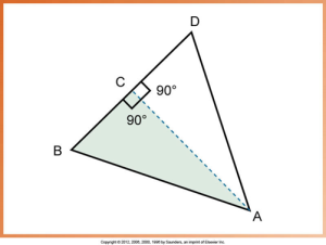
The diagram below displays the following:
- Angle A is bisected by line AC. Line AC is perpendicular to line BD
- Angle BAC is equal to angle DAC
- Angle ACB is equal to angle ACD.
- According to the rule of isometry, triangle BAC (shaded) is equal to triangle DAC

Bisecting Technique
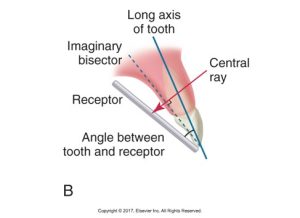
The receptor must be placed along the lingual surface of the tooth. The receptor’s plane and the tooth’s long axis form an angle at the point where the film contacts the tooth. Imaginary bisector bisects the angle formed by the receptor and the long axis of the tooth. The central ray is directed perpendicular to the imaginary bisector. And the two imaginary triangles that result are right triangles and congruent.
The hotspot image below consists of three parts, each demonstrating a step in dental x-ray bisecting techniques.
The image on the receptor is equal to the length of the tooth when the central ray is directed at 90 degrees to the imaginary bisector. A tooth and its image will be equal in length when two equal triangles that share a common side (imaginary bisector) are formed. The diagram below displays the bisecting technique in dental x-ray imaging. It shows a tooth, its long axis, an imaginary bisector, a receptor, and the angle between the tooth and the receptor. A central X-ray beam is directed through these elements.

Receptor Stabilization
This hotspot image demonstrates three parts of receptor stabilization for the bisecting technique.
Bisecting Angle Instruments (BAI)
BAI instruments include a metal indicator arm, plastic bite-blocks, and plastic aiming rings. The image below is of a variety of dental x-ray film holders and receptor stabilizers.

Below is a hotspot image of three types of dental receptor stabilizers.
Media Attributions
- Iannuci: Dental Radiography, 6th Edition, Chapter 20, CC BY-NC-ND

