20.2
For bisecting technique, a size 2 receptor is traditionally used. Anterior is the long portion in a vertical direction and posterior is the long portion in a horizontal direction.
Position-Indicating Device Angulation
Angulation is the alignment of the central ray of the x-ray beam in the horizontal and vertical planes.
Horizontal Angulation
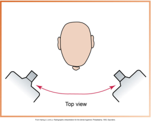
Horiztonal angulation is the positioning of the tubehead and direction of the central ray in a horizontal or side-to-side plane. Correct horizontal angulation is when the central ray is directed perpendicular to the arch’s curvature and through the teeth’ contact areas. Incorrect horizontal angulation is when there is overlapped contact areas.
Horizontal angulation of the position-indicating device (PID) refers to PID placement in a side-to-side (ear-to-ear) direction. The diagram below displays a head and two dental x-ray units positioned to demonstrate horizontal angulation.
 |
 |
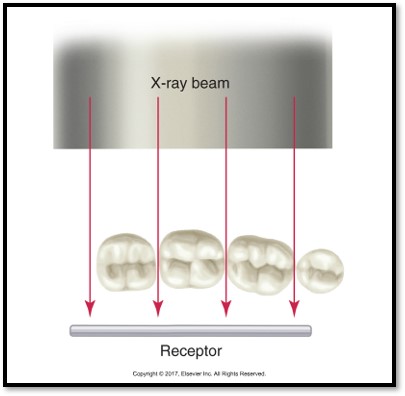
| This image illustrates the path of an x-ray beam directed through different tooth models to a receptor, highlighting proper angulation for dental imaging. | This image illustrates an x-ray beam directed from above onto models of teeth aligned in a row above a receptor, demonstrating dental x-ray techniques. |
Here is an image showing an example of what overlapped contacts look like on a dental x-ray.

Vertical Angulation
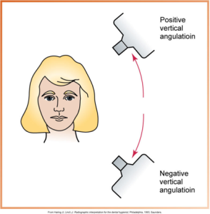
Vertical angulation is the positioning of the PID in a vertical or up-and-down plane. Correct vertical angulation results in a radiographic image that is the same length as the tooth, and incorrect vertical angulation results in a radiographic image that is not the same length as the tooth. It is important to remember that the measurement of vertical angulation is marked on the outside of the tubehead.
Vertical angulation of the position-indicating device (PID) refers to PID placement in an up-and-down (head-to-toe) direction. The diagram below displays positive and negative vertical angulations in dental x-ray imaging, featuring a head portrait and two x-ray units.
For vertical angulation, foreshortened images are radiographic images that appear shortened, which results from excessive vertical angulation and if the central ray is directed perpendicular to the plane of the receptor rather than to the imaginary bisector.
The hotspot image below displays foreshortened imaging.
For vertical angulation, elongated images are radiographic images that appear too long, which results from insufficient vertical angulation when the central ray is directed to the long axis of the tooth rather than to the imaginary bisector.
The hotspot image below displays elongated imaging.
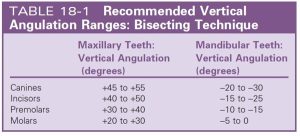
The table below displays the recommended vertical angulation ranges for the bisecting technique.
Rules for Bisecting Technique
The receptor placement must be positioned to cover the prescribed area of the tooth to be examined. The receptor position is against the lingual surface of the tooth, and the receptor exposure x-ray beam must be centered on the receptor to ensure all areas of the receptor are exposed or will result in partial or a cone-cut image.
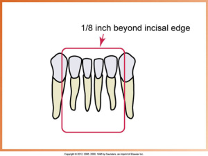
Approximately one-eighth of an inch of the receptor must appear beyond the teeth’ incisal edges, as shown in the diagram below.
Vertical angulation CR must be directed perpendicular to the imaginary bisector. Foreshortening occurs when there is excessive vertical angulation, and elongation occurs when there is insufficient vertical angulation. Horizontal angulation CR must be directed through the contact areas, or overlap will result.
Media Attributions
- Iannuci: Dental Radiography, 6th Edition, Chapter 20, CC BY-NC-ND
