19.3
Rules for Paralleling Technique
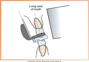
Receptor placement is positioned to cover prescribed areas, and receptor position is when the film must be positioned parallel to the long axis of the tooth – placed away from teeth & towards the middle of the oral cavity.
Vertical angulation is the central ray of x-ray beam must be directed perpendicular to the film & long axis of the tooth, and horizontal angulation is the central ray of the x-ray beam must be directed through the contact area between the teeth.
Film receptor exposure is when the x-ray beam must be centered on the film to ensure all areas of the film are exposed.
In the Iannucci & Howerton, Dental Radiography Principles & Techniques, 6th Edition textbook on page 170, refer to Figure 19-7.
 |
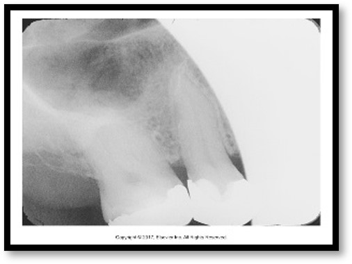 |
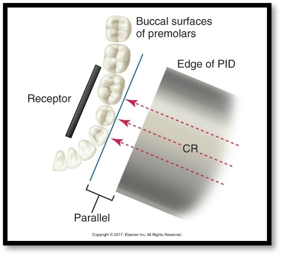
| Dental paralleling technique, showing a receptor parallel to the teeth’s buccal surfaces, with arrows indicating the direction of the central ray (CR) from the edge of the Position Indicating Device (PID) | A dental x-ray featuring a clear view of tooth structures and surrounding bone demonstrates the effective use of the paralleling technique. |
Horizontal Angulation
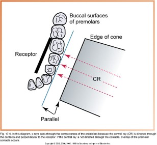
In the diagram below, x-rays pass through the contact areas of the premolars because the central ray (CR) is directed through the contacts and perpendicular to the receptor. If the central ray is not directed through the contacts, overlap of the premolar contacts occurs.
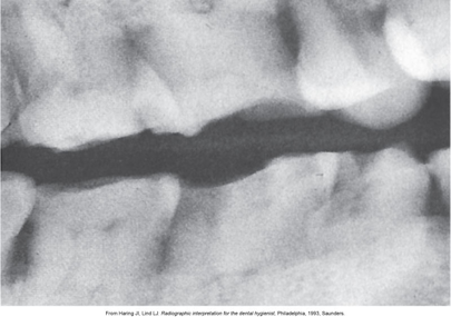
This image is a dental x-ray showing overlapping teeth, indicating incorrect horizontal angulation during the imaging process.
Step-by-Step Procedures Before
The step-by-step procedures before are:
- Patient preparation
- Equipment Preparation – before exposing, infection control procedures must be completed.
- Exposure sequence for receptor placements
- Receptor placement for paralleling technique
Patient Preparation
The procedure for patient preparation is the following steps:
- Explain the procedures.
- Adjust the chair.
- Adjust the headrest.
- Place and secure the lead apron.
- Remove all objects from the mouth.
- The midsaggital plane should be perpendicular to the floor.
The midsaggital plane (midline) is the imaginary midline of a body perpendicular to the floor. The midsaggital plane extends to the oral cavity and follows a line drawn through contacts of centrals up through the nose and down to the symphysis of the chin. A growing together of bones originally separate, as of the two pubic bones or the two halves of the lower jawbone.
Equipment Preparation
For equipment preparation, you must set the exposure control factors, open the sterilized package containing the beam alignment devices, and assemble the devices over a covered work area.
Watch this video on XCP holder assembly:
How to Assemble Dental X-Ray Rinns video transcript [word doc]
The hotspot image below displays the steps of XCP assembly.
Exposure Sequence for Receptor Placements
For the anterior exposure sequence, the size 1 receptor is small and easier for the patient to tolerate, and it is less likely to cause the patient to gag. A total of seven anterior placements using the size #1 receptor, which are four maxillary exposures and three mandibular exposures. If size #2 receptors are used, six films will be taken. You should stick to a sequence and do not interchange from patient to patient and make this sequence a habit for all radiographic exposures.
There are eight posterior placements for the posterior exposure sequence, which are four maxillary exposures and four mandibular exposures.
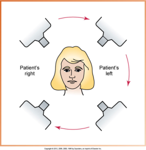
When exposing maxillary anterior receptors, work from the right to the left. Then, expose the mandibular anterior receptors from the left to the right. No unnecessary movements of the PID result.
Receptor Placement for Paralleling Technique
There is a specific area where the receptor must be positioned before exposure. This is dictated by teeth and surrounding structures.
Specific placements described in the chapter are for 15-receptor periapical series using size 1 receptors for anterior exposures and size #2 receptors for posterior exposures. Remember to have the PID close to the patient so the positioning of the ring will be quick, and also remind the patient to hold still during the exposure.
In the Iannucci & Howerton, Dental Radiography Principles & Techniques, 6th Edition textbook, starting on page 174, refer to Boxes 19-1 to 19-1, Figures 19-11 to 19-20, and Procedures 19-3 to 19-10.
Prescribed Placements for Anterior Periapical Receptors
The hotspot image below highlights four dental x-ray receptor placements that show different tooth alignments and positioning.
In the Iannucci & Howerton, Dental Radiography Principles & Techniques, 6th Edition textbook on page 174, refer to Box 19-1.
Prescribed Placements for Posterior Periapical Receptors
Modifications in Paralleling Technique
Shallow palate, bony growths, and mandibular premolar region are all modifications in paralleling technique.
It is very important for the dental radiographer to be competent in dealing with these types of situations. Utilizing cotton rolls, changing the vertical angulation, and the location of the receptor placement will assist the radiographer in taking a dental radiograph of diagnostic quality.
Shallow Palate
Two cotton rolls can be used, one placed on each side of the bite-block, and the vertical angulation can be increased by 5 to 15 degrees for shallow palates.
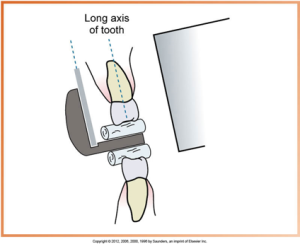
Shallow palate placement is the tilting of the bite-block, which results in a lack of parallelism between the receptor and the long axis of the tooth. The image is generally acceptable when the lack of parallelism is less than 20 degrees (as shown in the diagram below).
In the Iannucci & Howerton, Dental Radiography Principles & Techniques, 6th Edition textbook on page 184, refer to Figure 19-21.
As mentioned above, two cotton rolls can be used to position the receptor parallel to the long axis of the tooth.
In the Iannucci & Howerton, Dental Radiography Principles & Techniques, 6th Edition textbook on page 184, refer to Figure 19-22.
Bony Growths
Bony growths include maxillary torus and mandibular tori. The maxillary torus is when the receptor must be placed on the far side of the torus and then exposed, and the mandibular tori is when the receptor must be placed between the tori and the tongue and then exposed.
Maxillary Torus (unilateral)
A maxillary torus (torus palatinus) is a nodular bone mass seen along the hard palate’s midline. Below is an image showing the roof of the mouth and upper teeth with visible maxillary torus.
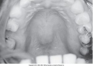
In the Iannucci & Howerton, Dental Radiography Principles & Techniques, 6th Edition textbook on page 184, refer to Figure 19-23.
Below is a hotspot image displaying a diagram with the positioning of dental x-ray equipment for capturing images of a maxillary torus and a sequence of dental x-rays displaying various upper jaw structures.
Mandibular Tori (bilateral)
Mandibular tori are bony growths along the mandible’s lingual aspect (tongue side). Below is an image showing the lower jaw and teeth with visible mandibular tori.
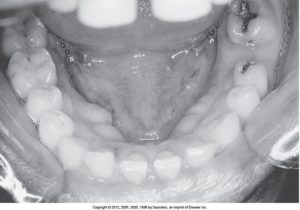
In the Iannucci & Howerton, Dental Radiography Principles & Techniques, 6th Edition textbook on page 184, refer to Figure 19-24.
Below is a hotspot image displaying a diagram that explains the position of dental x-ray equipment for imaging mandibular tori and a series of dental x-rays below showing various teeth and bone structures.
Radiopaque & Radiolucent
Radiopaque is the portion of an image that is white or light; a radiopaque structure resists the passage of the x-ray beam and limits the amount of x-rays that reach the receptor, and radiolucent is the portion of an image that is dark or black; a radiolucent structure permits the passage of the x-ray beam and allows more x-rays to reach the receptor.
Mandibular Premolar Region
Receptor placement is the receptor that must be placed under the tongue. Need to avoid impinging on muscle attachments and the sensitive soft tissues on the floor of the mouth.
Below is a hotspot image displaying the positioning of the XCP instrument in the sensitive mandibular premolar area.
Advantages of Paralleling Technique
Disadvantages of Paralleling Technique
Media Attributions
- Iannuci: Dental Radiography, 6th Edition, Chapter 19, CC BY-NC-ND
