Bite-Wing Technique Errors
For the bite-wing technique, errors include receptor placement, angulation, and PID alignment problems.
Receptor Placement Problems
The premolar bite-wing resulting image shows both the maxillary and mandibular premolars and distal contact areas of both canines and molar bite-wing; the resulting image shows both the maxillary and mandibular molars. To ensure that the distal surfaces of the canines are shown in the resulting image, the receptor must be positioned so that the front edge of the receptor is aligned with the midline of the mandibular canine.
 |
 |
| An image of correct receptor placement for the premolar bite-wing. |
An image of correct receptor placement for the molar bite-wing. |
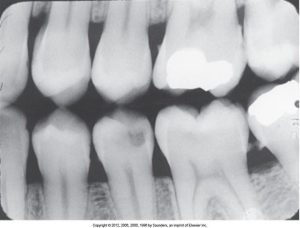
Incorrect Receptor Placement of Premolar Bite-Wing
The receptor may occur with digital sensors or film, and the bite-wing technique may occur when a beam alignment device or bite-tab is used. It will appear as if the distal surfaces of the canines are not visible on the image. The cause of this is the bite-wing receptor was positioned too far posteriorly in the mouth, which can be corrected by making sure the anterior edge of the bite-wing receptor is positioned at the midline of the mandibular canine. When using a digital sensor, capturing the distal surfaces of the canines during bite-wing exposure can be challenging.
Here is an image of incorrect receptor placement for the premolar bite-wing.
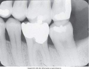
Incorrect Placement of Molar Bite-Wing
The receptor may occur with digital sensors or film, with the bite-wing technique may occur when a beam alignment device or bite-tab is used. The third molar regions are not visible on the image. The molar bite-wing must be centered over the mandibular second molar, and to ensure accuracy, the front edge of the receptor needs to be aligned with the midline of the mandibular second molar. The cause of incorrect placement is the bite-wing receptor was positioned too far anteriorly in the mouth and to correct this, the anterior edge of the bite-wing receptor is positioned at the midline of the mandibular second premolar.
Angulation Problems
A dental radiographer must be prepared to choose the correct horizontal and vertical angulations. Incorrect horizontal angulation results in overlapped interproximal contacts, and incorrect vertical angulation results in distorted images
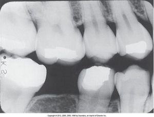
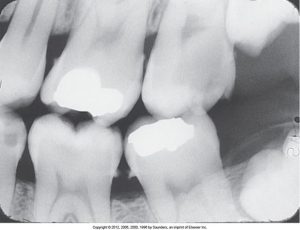
Overlapped Contacts: Incorrect Horizontal Angulation
For incorrect horizontal angulation for overlapped contacts, the receptor may occur with digital sensors or film. The bite-wing technique may occur when a beam alignment device or bite-tab is used. Overlapped contacts will appear on the image because the central ray was not directed through the interproximal spaces. This can be corrected by directing the x-ray beam through the interproximal spaces. If the overlapping is more pronounced in the posterior half of the image, the PID was pointed too much from the mesial toward the distal. Proper use of a Rinn XCP bite-wing instrument minimizes errors in horizontal angulation.
The image below displays overlapped interproximal contacts resulting from incorrect horizontal angulation.
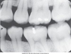
Distorted Image: Incorrect Vertical Angulation
The receptor may occur with digital sensors or film for incorrect vertical angulation. The bite-wing technique may occur when a bite-tab is used, and the images appear distorted because the vertical angulation was incorrect. This can be corrected by always using a +10-degree vertical angulation with the bite-wing technique. The positive angulation compensates for the slight lingual tilt of both the maxillary teeth and the upper half of the receptor caused by the hard palate.
The image below shows incorrect vertical angulation, which causes the images to appear distorted.
Position Indicating Device Alignment Problems
If the PID is misaligned and the x-ray beam is not centered over the receptor, a partial image results, known as a “cone-cut.”
Cone-Cut with Beam Alignment Device
For cone-cuts with a beam alignment device, the receptor may occur with digital sensors or film. The bite-wing technique may occur when a beam alignment is used, which displays a clear area on the image caused by the PID not correctly aligned with the beam alignment device, and it is made sure that the PID and the aiming ring are aligned.
Cone-Cut without Beam Alignment Device
For cone cuts without a beam alignment device, the receptor may be used with digital sensors or film, and the bite-wing technique may occur when a bite-tab is used. It will appear as a clear area on the image. This is caused by the PID not being directed at the center of the receptor. This is corrected by making sure the x-ray beam is centered over the receptor. A cone-cut image is more likely to occur when a bite-tab is used because there is no aiming ring to guide PID placement.
Miscellaneous Technique Errors
Miscellaneous technique errors may be seen on both periapical and bite-wing images. The following errors are:
- Bending
- Creasing
- Debris accumulation
- Phalangioma
- Double accumulation
- Movement/motion unsharpness
- Reversed/backward placement
Go through the slides to learn more about each technique error.
Wired Cable Issues
Wired cable issues occur with the receptor when it is exclusively used with direct digital sensors. Paralleling, bisecting, or bite-wing techniques may occur. This causes the intraoral sensor to be linked to a computer via fiberoptic cable; if the sensor is placed with the cable between the sensor and the source of radiation, an outline of the cable will be seen. This can be corrected by most manufacturers of direct digital imaging systems providing a clamp on the metal indicator arm of the beam alignment device and also checking to make sure the cable is secure, the patient is not biting on the cable, and that the cable is out of the beam of x-radiation before each exposure.
Media Attributions
- Iannuci: Dental Radiography, 6th Edition, Chapter 22, CC BY-NC-ND