Experiment 1: Distillation
Purpose
- Operate the distillation column at total reflux.
- Determine the temperature and concentration profiles of the column when steady-state has been attained.
- Calculate the number of theoretical stages required to achieve the observed separation from the provided and measured data.
Introduction
Distillation is a form of physical separation. Typically, a mix of two miscible liquids is subjected to enough heat to cause the more volatile of the two liquids to evaporate and then condense in a separate unit. Because the two liquids are typically very alike in many physical and chemical properties, the separation needs to take place over a number of stages aligned up the length of the column. In a distillation column, these stages are actually trays of various configurations where the vapours rising up the column come in contact with a portion of the condensed liquids running back down. At the site of each of these trays, good mixing of the vapour and liquid occurs and a vapour-liquid equilibrium is established. Going up the height of the column, there is an increasingly higher concentration of the more volatile component. At the top of the column, the percentage of the more volatile component can be as high as 96%. Figure 1 below shows the distillation unit in the lab.
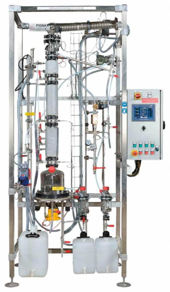
Figure 1: DVI/3000 Pignat distillation unit
The video below is a quick overview of distillation columns:
https://youtu.be/M7AL7-44YTc
Distillation Video
Watch the video below for more explanation of the steps of what you would be doing in the lab and more explanation about the experiment. (The link would open a new tab for the video).
Experiment Video: Distillation
System Description
In the distillation column in the E030 laboratory, the trays contain a bubble cap. With this design, there is an overflow that maintains a level of liquid on a tray. Vapour rises up the column and is forced by the cap to pass through slots that are below liquid level and thus to bubble through the liquid. There are 15 DN50 bubble cap trays distributed through the 3 sections of the column. Industrial units have many caps on each tray and usually many more trays. Alternatively, some industrial units feature packed columns.
Unlike many industrial units, the lab apparatus has five sampling valves across the column with the first one at the bottom of the instrument (the heating kettle), three along the column, and one on the top of the unit to allow for sampling the final distilled product. A thermocouple at each sampling level enables recording the temperature.
The HMI of the system is positioned on the control cabinet on the right-hand side of the unit. The distillation process can be also controlled from the remote computer connected through the ethernet cable or through the wireless network.
For more information about bubble cap trays, watch the segment: 5:54 - 7:54 of the video below:
The following figures highlight the different elements, valves, and other measuring components of the distillation unit used for this experiment. Be sure to be familiar with the main parts of the unit as well as the valves.
System
Figure 2: DVI/3000 distillation unit principal element identification
Manual Valves
Figure 3: DVI/3000 distillation unit principal valve identification
Measuring Components
The components highlighted in the figure below include the temperatures, flow rate, and pressure measurements with the level alarm detections.
Figure 4: DVI/3000 distillation unit measuring components identification
Control Cabinet
Figure 5: Control cabinet
HMI User Interface
Check your Understanding
You can try the following questions for practice about distillation and the system to be used for the experiment in the quiz below:
Experimental Procedure
The kettle (also known as "still pot") contains a mixture of ethanol and water and is usually replenished by lab staff. If the kettle is empty, contact your instructor for the proper instructions.
1) Turning on the system
- Turn on the exhaust fan in the lab (the switch is located on the left-hand side of the distillation column on the wall).
- Turn on the control cabinet (Refer to Figure 5).
- Turn the main switch on (you should see the white light indicator turned on).
- Push the green button on (general power).
2) Opening the cooling water to condenser
- Check that the hoses for the cooling water are directed to the drain in the laboratory, so that water will drain into the trench.
- Open the main water supply valve in the lab and then open the feeding valve of the unit V16 to make possible the cold water circulation.
- Check the water supply pressure on the pressure gauge (the network pressure into the circuit should be 2 bars).
- Check if the limit switch for the minimum water flow rate which is attached to the rotameter is set (you can slide it up or down the guides behind the rotameter) on the level of 100 L/h. Adjust if necessary.
- Adjust the water flow rate with the needle valve V18 to a value between 100 L/h and 200 L/h. Ensure that water is indeed draining into the trench.
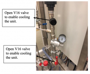
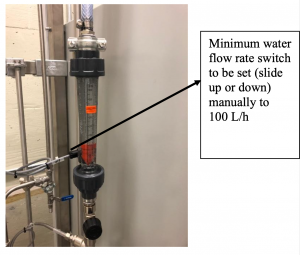
Figure 8: V16 water supply valve Figure 9: Rotameter with needle valve V18 Warnings:
If the cold water flow rate is too low for the quantity of vapours that reach the condenser and have to be condensed, the general vent temperature will increase. The thermostat will then detect a high temperature alarm and stop the dosing pump and the kettle heating.Solution:
Increase the water flow rate to 300 L/h to accelerate the cooling of the general vent thermostat.
In case of high temperature alarm on the thermostat, always think about the causes:- Cold water flow rate not adjusted correctly.
- The unit has been put under reduced pressure whereas it is not authorized.
Restart the distillation unit.
3) Charging the unit with ethanol-water mixture
- If the kettle is empty and you were asked by the instructor to charge the feed mixture into the unit, make sure that the kettle temperature is below 30°C. This should be indicated on HMI TI1.
- Check that valves V9 and V10 are closed.
- Open valve V8 and open the charging port by unscrewing the tap.
- Charge the kettle up using a funnel to the overflowing level (when you see that the liquid is overflowing to the residue glass receiver; ~3 Liters).
- Replace the tap and screw it (manual screwing only) enough to make sure that there is no leakage.
- It is necessary to cool both distillates and residues if you store them into the receivers and if you want to take a sample. Open V17 by 2 turns to feed both coolers with water.
4) Heating the unit
- Heating the ethanol-water mixture can be accomplished in two control modes: manual or automatic. To access the controller, click on the "DPI1 dP column" tab and select automatic mode. Type 1200 kPa as the setpoint, making sure that Auto mode is selected.
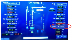
Figure 10: Setting up the heating of the column Automatic mode:
In automatic mode, the user enters the differential pressure on the column setpoint and the power output to the heater varies depending on the current pressure differential in the column.Manual mode:
In manual mode, the user enters the % of the output on the controller. 100% output will feed 2 kW of power to the heater, while 50% setpoint will send 1 kW power to the heating elements. - To start heating, press the heating button on the control cabinet.
- Observe if there is excessive flooding on any of the trays. Lower the differential pressure setpoint on TIC6 so that there is adequate bubbling at each tray (Do not set it lower than 900 Pa).
- To stop heating, adjust the setpoint on the controller to 0 on the HMI and press the stop button on the control cabinet.
5) Reflux mode setting
- Set the three-way switch "reflux / cycle / draw off" to the REFLUX conditions in the column.
- The solenoid valve on the top of the column will be set directing the flow of the condensate back to the column and no product will be removed as distillate.
Do not put the switch to DRAW OFF or CYCLE at this stage:
- Setting the switch to DRAW OFF will send all the distillate to the distillate receiving container through valve V15.
- Setting the switch to CYCLE will allow, with using the controller, to define the Reflux ratio [latex]R=\frac{L}{D}[/latex] (L-part of the liquid flowing back to the column at the level of reflux valve; D-part of the liquid drawn off - product removal) and partial removal of the distillate (product) from the system.
6) Sampling of liquids and measurements
- Once you see the liquid and vapours on each tray and steady-state is achieved (steady temperatures in the column) you are ready to collect samples to measure the ethanol concentration across the column.
Wear insulating gloves as the samples will be hot!!!
- Sampling during the experiment is necessary to characterize the column. On the DVI/3000 unit, you can sample the following phases:
- Hot residue from the kettle opening V9
- Cooled residue opening V11 (for continuous process only)
- Cooled distillate opening V14
- Feeding mixture opening V1 (for continuous process only)
- Mixtures into the column opening V5, V6, V7
Note:
To take samples of the mixtures in equilibrium into the column, it is very important to open the valve very slowly so that you do not create a depression at the level of the valve and break the column equilibrium. Using the sampling valve, you will collect a sample of the liquid phase in equilibrium into the plate. Be careful as the samples collected from the column will be hot. - Collect 10 mL sample into the glass container. Cap the container right after collecting the liquids. Once the sample has cooled, use the digital densitometer and determine the ethanol concentration % on mass basis and report it to your notebook.
- Refer to the operating manual for the densitometer or ask your instructor for directions.
- You should have the following 5 samples collected:
- V9 (hot liquid!)
- V5, V6, V7 (hot liquids!)
- V14 (since the column operates at total REFLUX, there will be no distillate. It might be necessary to set the reflux switch to CYCLE with reflux ratio on the Head Control to manual mode with setpoint 60% which would give 1.5 reflux ratio).
7) Complete the experiment
- Once the samples are collected, start cooling the system by adjusting the setpoint on the controller DPI1 dP to 0 on the HMI, and in 10 minutes press the stop button on the control cabinet.
- Once the temperature in the column drops to 40°C (at the top of the column on TIC5), stop the cooling water by closing the water valves and shut down the cabinet.
- Turn off the exhaust fan in the laboratory.
Report
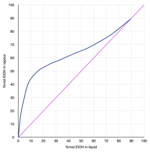
- Using the data from Table 1 from the Appendix, plot a y vs. x diagram, where y is the % mole of EtOH (Ethanol) in the vapour and x is the % mole of EtOH in the liquid.
- Convert the mass % of ethanol read from the densitometer from all the sampling locations to mole % (show your sample calculation). Tip: Check out the calculation example from the quiz above.
Table 1: Ethanol mass %w/w in %mol Location [EtOH] %w/w [EtOH] %mol Reboiler Column bottom Column middle Column top Distillate (Final sample) - As you collected only liquid samples, show on your graph the x values (concentrations of ethanol in liquid phase at a given sampling location) and read the corresponding vapour y concentration of ethanol from the vapour-liquid equilibrium graph; show those values in the excel table.
Table 2: %mol EtOH in liquid and in vapour Location [EtOH] %mol in liquid [EtOH] %mol in vapour Reboiler Column bottom Column middle Column top Distillate (Final sample) - The operating line for a distillation under total reflux is the line of equation y=x. Based on the equilibrium curve and your xD (distillate) and xR (residue) count the number of theoretical plates, using the McCabe - Thiele method described in the appendix.
- Calculate the efficiency of the column, given as:
[latex]Efficiency = \frac{number\,of\,theoretical\,plates}{number\,of\,actual\,plates}\times 100\%[/latex]
Recall that the kettle counts as a plate; hence the "number of actual plates" in the column for this calculation is 15 + 1.
- Plot a concentration of %mole ethanol vs. temperature and answer the following questions:
- What is the boiling point of water and ethanol?
- Which part of the column would you collect the highest and the lowest concentration of EtOH?
- Which part of the column would have the lowest and the highest temperature?
Appendix
The video below would help in the plotting and creating the steps for your data:
Water/Ethanol liquid vapour equilibrium data (at Patm)
|
Figure 11: Water/Ethanol vapour liquid equilibrium at atmospheric pressure |
||||||||||||||||||||||||||||||||||||||||||||||||||||||
McCabe-Thiele Method
- Use the vapour-liquid equilibrium data of Table 3 to plot the equilibrium curve.
Make sure that the graph is square! (i.e. that the unit length of the x-axis is equal to the unit length of the y-axis.
- Plot the compositions of the kettle (xb) and the condensate (xd).
- Draw a vertical line from xb to meet the equilibrium curve.
- Draw a horizontal line from A to B to meet the diagonal.
- From B, draw a vertical line to meet the curve at C.
- Continue this stepping until the line from xd is intersected.
- Count the number of steps. In this example, the number of steps is 3.5.
- The number of theoretical stages is equal to the number of steps.
- The last step may be a partial step and should be estimated (0.5, 0.25, etc.).
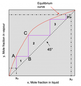 |
| Figure 12: Example graph result of the McCabe-Thiele method |

