Experiment #2: Resolving helical structures
2. What to do during the lab?
Lab Goal: Determine the structure of three different objects (a hair, a diffraction grating and a spring) using both microscopy and diffraction.
2.1 Imaging
Goal: Acquire calibrated images of your three objects, and determine the size and spacing of their characteristic features directly from these images.
Equipment: Hair. Diffraction grating. Spring. Ruler. Optical microscope and camera. Calibration slide.
Bring: Cell phone with camera.
Instructions:
- If the spring is large enough for you to resolve its coils, take a picture of it beside something you can use for scale (e.g. a ruler), using a cell phone.
- If you can, use the microscope at the lowest magnification to acquire an image of the spring (so you can precisely measure the thickness of the wire it is made of). Don’t forget to also acquire an image of the ruler on the calibration slide!
- Use the microscope to acquire an image of a hair and of the diffraction grating. When using an appropriate magnification, you should be able to resolve the closely spaced parallel slits that make up the diffraction grating.
- Use ImageJ to determine the thickness of the hair and the spacing between slits in your diffraction grating.
- Use ImageJ to determine the four parameters defined in Fig. 1 (pitch, helix diameter, wire diameter and helix angle) for your spring. In addition to the tools you already know, the angle tool that can be found on the toolbar will be useful.
2.2 Diffraction
Goal: To solve the structure of a helix (the spring) using diffraction, just as Franklin, Watson and Cricks did for DNA. Here we will use visible light instead of x-rays. A schematic of the set-up you will use is shown in Fig. 3, and a picture of the real set-up is shown in Fig. 4.
Equipment: Hair. Diffraction grating. Spring. Laser pointer. Polarizer. Two lenses. Beam blocker. Paper and cardboard to be used as viewing screen. Tape. Rulers (short and long).
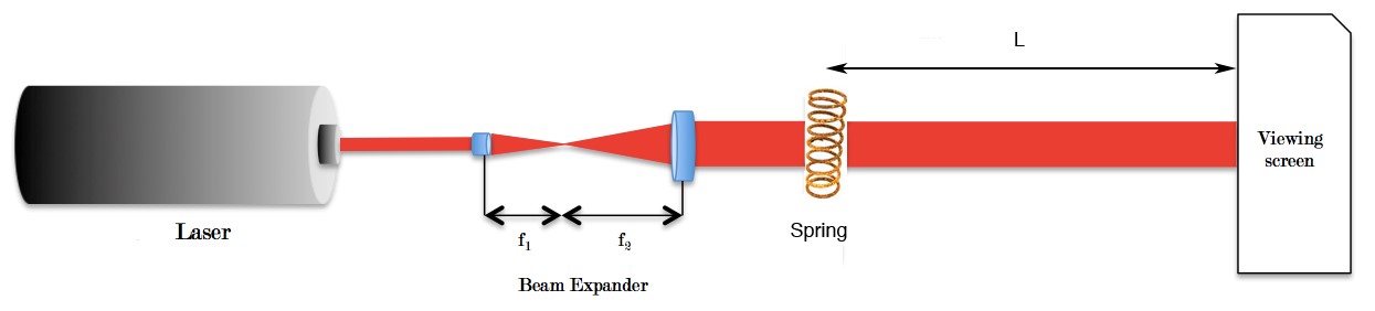
Figure 3: Schematic diagram of the experiment.
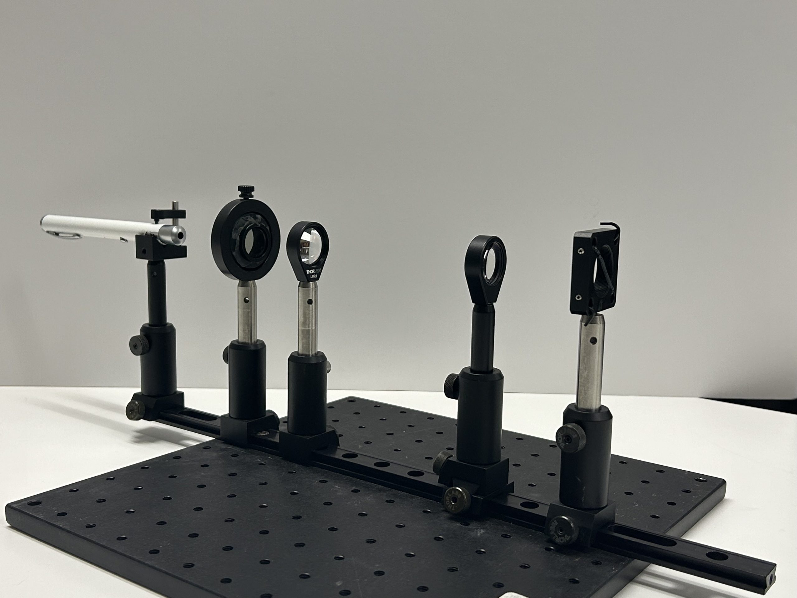
Figure 4: Picture of the actual set-up used to measure the spring diffraction pattern. From left to right you can see: 1) laser pointer (held in place by a laser holder), 2) polarizer (used to adjust the brightness of the laser beam), 3) first and 4) second lens (together making up the beam expander), 5) spring holder, 6) beam blocker. The first 5 elements are mounted on a rail, allowing to easily adjust their position along the optical axis.
Instructions:
- First, obtain a diffraction pattern for the hair. You do not need use the lenses in this case, instead place the hair right after the polarizer, directly in the path of the beam. Use a pole to place a screen to capture the diffraction pattern, far enough for its features to be well separated, but close enough for the intensity to be sufficiently high. Record the distance between object and screen (see Figure 5). Take a picture of the diffraction pattern with your cell phone, making sure to include a scale in the image.
- Repeat the same procedure to obtain a diffraction pattern for the grating. Measure all the relevant distances with a ruler. You can quickly calculate the diffraction angle for the first order diffraction peak, and from it the spacing between the slits in your grating.
- Finally, try to obtain a good diffraction pattern for the spring. For this, you will need to illuminate as many repeats of the helical spring as possible. This means that the diameter of the beam coming out of the laser pointer needs to be expanded. It also needs to be close to collimated (meaning that it should neither be converging nor diverging). To achieve both expansion and collimation, you can use two lenses, with focal lengths
 and
and  . When the focal planes of the two lenses coincide (in other words, when the distance between the two lenses is exactly
  ), we obtain a collimated beam whose radius has been expanded by
  (see Fig. 3). Adjust the distance between the lenses to make sure you have a collimated beam.
 - Place your spring in the path of the collimated expanded beam (see Fig. 3). Once the spring is correctly positioned, you can readjust the position of the second lens in order to concentrate (focus) more light onto the spring, after which you should be able to see a diffraction pattern projected on the wall at the other side of the room. This pattern should look like the famous diffraction pattern Rosalind Franklin obtained from DNA fibres: an X, with diffraction fringes on each of the branches of the X.
- Place a screen or a piece of paper on the wall where the diffraction pattern appears – the further away from the spring you place the screen, the larger (and easier to analyze) the pattern will be. At this point, you can further play with the position of the lenses to make the diffraction pattern sharper.
- To improve the clarity of your diffraction pattern, you can place a beam blocker after the spring to remove the very bright spot in the center of the diffraction pattern (which corresponds to light that has not been diffracted).
- Take a picture of your diffraction pattern. Don’t forget to add a scale (for example, a ruler, or millimetric paper) in the picture, so that the distance between diffraction fringes can be measured exactly later.
- Once again, make sure you measure the distance between the spring and the screen, so that you can calculate diffraction angles later.
Figure 5: Pictures demonstrating the correct positioning for the laser distance meter for measuring the distance between the object and screen.
2.3 Analysis
- Use ImageJ to characterize the diffraction patterns that you have photographed. For each pattern, you will want to measure the distance between diffraction peaks (try drawing a line that passes through the center of the diffraction pattern and through the peaks you want to localize, then select Analyze > Plot profile). In the case of the spring, you should also measure the angle between the two branches of the X (use the angle tool on the ImageJ toolbar).
- From this information, calculate the dimensions of the hair (thickness), grating (distance between slits) and of the spring (helix angle, pitch, diameter). You can find ideas about how to conduct this analysis in the companion tutorial on DNA diffraction.
- How do the dimensions you calculated from the features of the diffraction pattern compare to those you directly measured from microscopy images?
Lab 2 Notes/FAQs
- Imaging with both your microscope and taking clear, scaled photos with your camera is important.