Experiment #2: Resolving helical structures
1. Introduction and background
Helices are found everywhere in nature. Maybe the most well-known example of a natural helix is the double helix formed by DNA, whose structure was famously solved using x-ray diffraction.
In this lab, we will characterize the structure of a small helical spring in two ways. In part 1, you will obtain an image of the spring. In part 2, you will use a laser pointer to produce a diffraction pattern from the spring.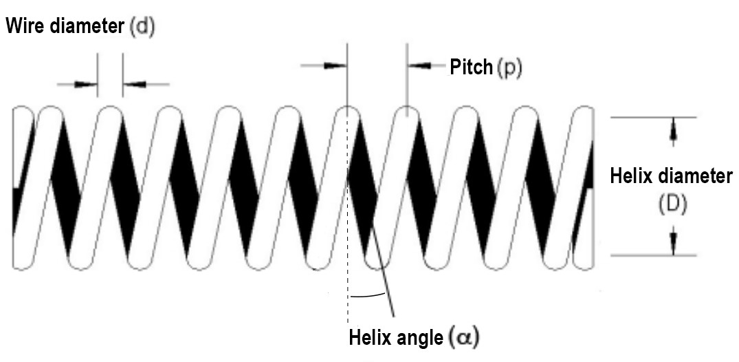
Figure 1: Schematic diagram of a helical spring seen from the side. The pitch (p), helix diameter (D), helix angle ( ) and filament diameter (d) are indicated on the diagram.
1. Background
1.1 General structure of a helix
A helix can be defined in mathematical terms by a set of parametric equations:


These equations show that one needs only two parameters to define the path of a helix: its pitch ( ) and diameter (
 ). From those parameters, one can calculate the angle (
 ) that an helix segment make with the plane perpendicular to the axis of the ellipse:

A full description of a real helix might require additional parameters. For example, a helical spring (as represented in Fig. 1) will also be characterized by the diameter of the wire forming the spring ( ).
).
1.2 Diffraction
Diffraction by a single object:
If coherent light (wavelength  ) is shone on an object, diffraction from features with a size comparable to or smaller than the wavelength of the light will cause some of the light to significantly change direction, a phenomenon called diffraction.
As a rule of thumb, a feature with size  will cause first order diffraction at an angle of the order of
  . For example, if the object is a simple elongated slit with width , the diffraction pattern (that is the intensity of the diffracted light as a function of angle,
  ) has a central peak with angular radius
From the full diffraction pattern, , one can in principle reconstruct the structure of the object. However, the light diffracted by a single small object is often too weak to be detected.
Diffraction by a regular array of objects:
Thus instead of studying diffraction by a single object (single slit, single protein), we often study diffraction by a large collection of that same object, organized in a regular array (e.g. diffraction grating, protein crystal). The diffraction pattern generated by a regular array of objects is made of a series of very sharp spots (corresponding to directions in which light diffracted by each individual object in the array has constructive interferences). The larger the number of objects illuminated by the light in the array, the sharper the peaks.

Figure 2: Left: Schematic diagram of a diffraction experiment with a diffraction grating. The grating diffracts light in a series of different directions, on either side of the optical path. Right: Schematic diagram of the diffraction pattern created by a diffraction grating, showing light intensity as a function of angle. The dashed line shows the envelope of the diffraction pattern. (Image credit: physicsopenlab.com)
In a diffraction pattern, two things give information about the object diffracting the light:
The first is the position of the diffraction peaks. This is best illustrated using the simple example of the diffraction grating: if the slits in the grating are spaced by a distance a, then the first diffraction peak is found at an angle , the second at an angle  , etc… The position of the peak therefore allows determining the distance between the repeated unit in the object (slits in the grating, coils in a spring, proteins in a protein crystal, etc…).
The second is the intensity of the diffraction peaks. It is characterized by the envelope of the diffraction pattern, i.e. the smoothest curve that you can draw that passes at the intensity maximum of all the diffraction peaks. The envelope is nothing else than the diffraction pattern of a single of the repeated feature in the object (e.g. a single slit in the grating, a single coil in the spring, a single protein in a protein crystal…). The intensity of the diffraction peaks therefore allows determining the structure of the repeated features (e.g. width of a single slit, thickness of a coil, position of every single atom in a protein…).
1.3 Precautions to take during this lab
- Be careful when handling lasers, even laser pointers such as the ones we will use in this lab.
- Use a low laser intensity when aligning your set-up, and a higher intensity only when photographing your diffraction pattern.
- Never look directly into a laser beam.
- Avoid shooting laser beams in the direction of other people and make sure you give plenty of warning to others when using lasers.
- Avoid wearing metallic rings that might reflect laser beams in unexpected directions.
- Turn off your laser pointer when you are not using it.
- Handling lenses. Never put your fingers on a lens, as they are hard to clean and fingerprints on their surface noticeably decrease their performance.