Experiment #1: The light microscope
1. A short introduction to light microscopy
This introductory experiment on the functioning and alignment of a light microscope is greatly inspired by the book Fundamentals of light microscopy and electron imaging by Douglas B. Murphy, which is an excellent reference if you need more information about microscopy. Another excellent resource about microscopy is the online Nikon University Microscopy (http://www.microscopyu.com).
1.1 What is a light microscope?
Light microscopes are instruments which use visible light (i.e. light with a wavelength comprised between ~380 nm and 740 nm) to produce enlarged images of objects. They are nothing more than a set of high quality lenses (with very specific properties and organized in a very specific way) coupled with a lamp for illumination and a stage for placement of the object to be observed.
Most microscopes today are compound microscopes, which means that they use two lenses (the objective lens and an eyepiece and/or a tube lens) to form images. Two other very important lenses complete the set of lenses found in a modern microscope: the condenser lens and the collector lens, which together control the illumination of the sample by focusing the light coming from the lamp onto a small area of the sample. Note that some of these “lenses” are in fact complex sets of lenses assembled together, allowing for a better compensation of different types of optical aberrations.
There are two main types of microscopes: upright microscopes, where the objective is placed above the sample, and inverted microscopes, where the objective is placed below the sample. For this class, we will use an upright microscope (Fig. 1a).
1.2 Conjugate focal planes
An important concept in microscopy is that of conjugate focal planes. There are two sets of conjugate focal planes in a microscope. The first four conjugate planes are called field planes (Fig. 1b). The condenser focuses the light coming from the light source from the field diaphragm plane to the object plane (or specimen plane), where the sample itself resides. The objective forms a first real image of the sample in the intermediate image plane, and the tube lens (or the eyepiece plus the lens in your eye) reforms this image in the image plane (where we can place a digital camera chip, or where your retina is). The second set of conjugate planes are the so-called aperture planes (Fig. 1c). They consist of the lamp filament plane (where the lamp filament is), the condenser aperture plane (also called condenser diaphragm plane) placed just at the aperture of the condenser, the objective rear focal plane (at the back aperture of the objective) and the eyepoint or exit pupil of eyepiece plane (where the iris of the eye would be if using an eyepiece, or where the camera lens would be if using a camera system).
If a ray of light is focused in one field plane, it is focused in all the other field planes (that’s what is meant by focal conjugate planes). Same for the aperture planes. When looking through the eyepiece of a microscope, one concurrently sees all the field planes (this means that if the microscope is aligned properly you can see both the sample placed in the object plane and the field diaphragm). By removing the eyepiece, or by using instead of the eyepiece a special lens known as eyepiece telescope, one can see instead all the aperture planes (this means that for a well aligned microscope you can then see the lamp filament, the aperture diaphragm or phase ring and the phase mask). Aligning a microscope means that all the optical elements that can be adjusted (usually the lamp, the field and aperture diaphragms, the phase ring and mask, the specimen, the camera) coincide with the appropriate field or aperture planes and are properly centred on the optical axis.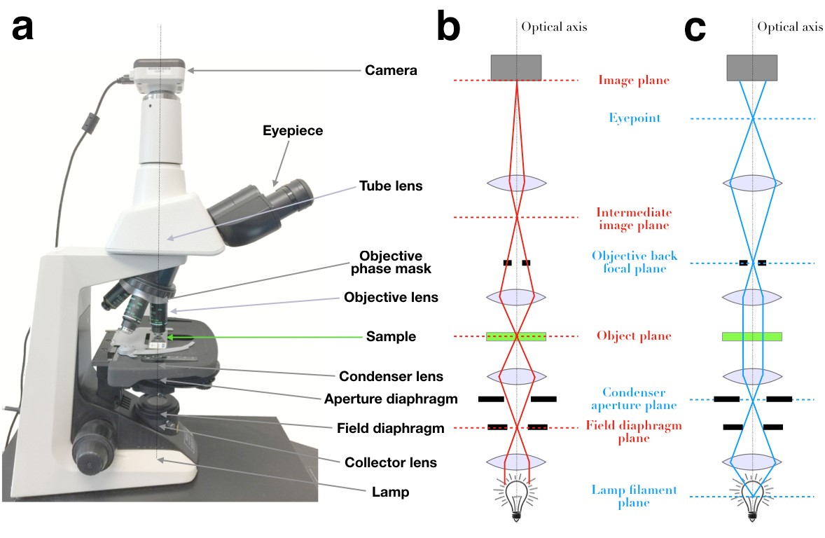
Figure 1: a) Picture of the Nikon Eclipse E200 upright phase microscope used in the lab. b) Simplified schematic representation of the microscope showing the 4 conjugate field planes (indicated by red dashed lines) and the image-forming light path. c) The 4 conjugate aperture planes (indicated by blue dashed lines) and the illumination light path.
1.3 Magnification and resolution.
Magnification. The magnification of a microscope varies depending on the objective used. The magnification indicated on the objective,  , is the total magnification due to both the objective and the tube lens. Thus a 10x objective will produce a 10x magnified image of the object in the image plane. The indicated magnification is approximate, and in order to make precise measurements one should calibrate the microscope.
Numerical aperture. The numerical aperture (NA) of an objective is a dimensionless number related to the largest angle ( ) over which it can collect light, and the refraction index (
 ) of the medium between the objective and the sample. Namely: NA
  .
.
Resolution. The theoretical resolution of a microscope (i.e. minimum size of the features that can be resolved with the microscope) operated with a particular objective can never be better than: 
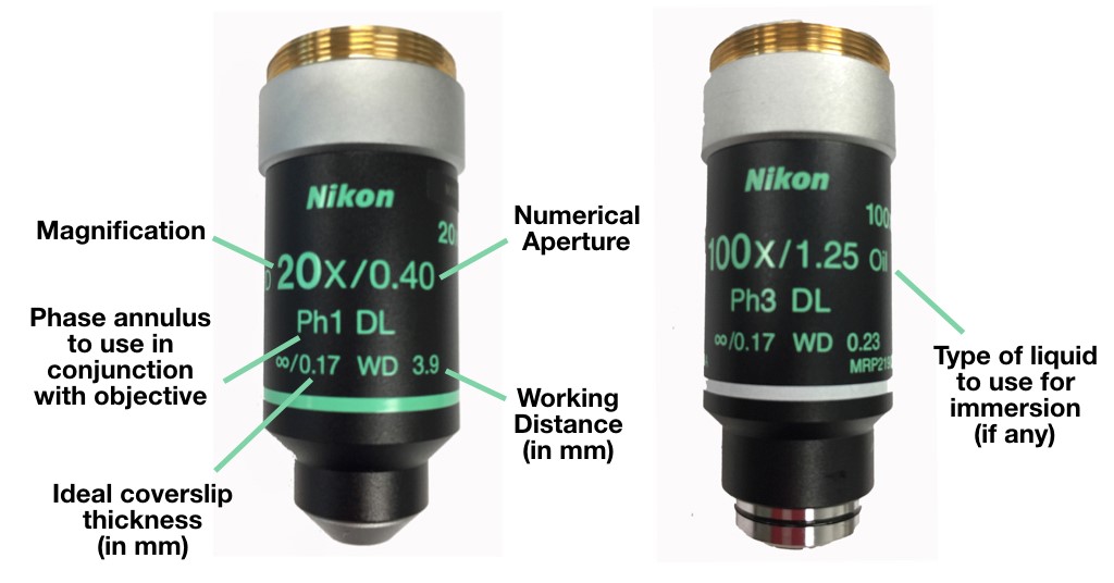
Figure 2: The magnification and numerical aperture of a microscope are indicated on the objective (together with the working distance and ideal coverslip thickness). For phase objective, the size of the phase ring to be used is also indicated. In addition, the mention “water” or “oil” is shown for water-immersion or oil-immersion objectives.
1.4 Improving contrast with phase microscopy.
Contrast. In a black and white image, the contrast is defined as the percentage difference between the intensity of the feature of interest and that of the background (adding colour to objects is one way to improve contrast). Our eyes need a contrast of at least 2% to distinguish an object from its background. Contrast is created by the fact that light interacts differently with different types of materials.
Phase microscopy. Biological samples often have an index of refraction that is very similar to that of water, and thus generate very little contrast in the light microscope. Cell biologists therefore often use phase contrast microscopy, a technique which allows to transform variation in the phase (rather than the intensity) of the light passing through the sample into contrast variations. This is done by using a cylindrical illumination produced by a ring placed in the condenser aperture plane, and a phase plate at the back aperture of the objective. The size and position of the two rings must match. When they do, a significant contrast enhancement is achieved.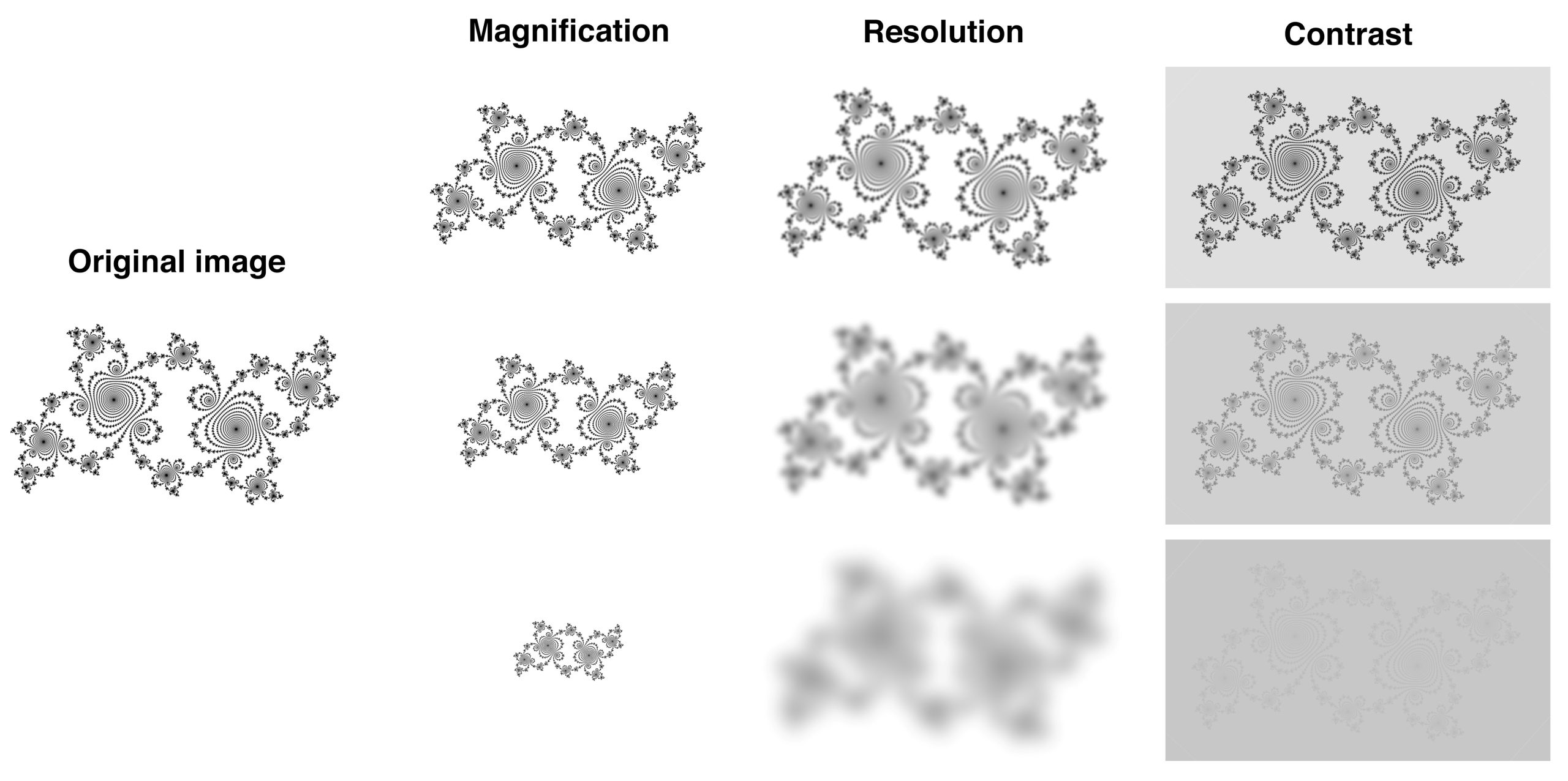
Figure 3: Illustration of the concepts of magnification, resolution and contrast, using the image of a fractal structure. The original image (credit: Adam Majewski) can be seen at the left, while the effect of decreasing magnification, resolution or contrast, is shown in the second, third and fourth column.
1.5 Precautions to take when handling a microscope
- Never, ever, touch the surface of a lens with your fingers. The surface of lenses is extremely fragile, and is often covered with expensive coatings. Scratches, grease and dirt on lens surfaces are the first cause for microscope performance degradation.
- Do not drop, bend, or twist objectives.
- When focusing, be careful not to touch the sample with the objective lens (this can be an issue when working with high NA objectives, which have short working distances).
- After using an oil objective, make sure that oil does not get on the lens of the other objectives (this can happen if switching from an oil to an air objective without first cleaning the sample). Ask help from the TA if your are unsure how to clean oil from a sample or an objective.